Combi Unit Genius Controlled Residential Ventilation with Heat Recovery, Heating, Hot Water Generation, Cooling Installation, Operation and Maintenance Instructions for qualified installers EN page 1 - page 126
The data stated in these operating instructions are merely for the product description. Information about a certain property or suitability for a certain purpose of use can not be derived from our information. The information does not release the user from his own assessments and examinations. It must be noted that our products are subject to a natural wear and ageing process. Systemair GmbH also reserves all rights in the case of registration of industrial property rights.
Table of Contents 1 General Information..................................................5 8.4 Hot Water Module....................................................... 40 1.1 List of Information..........................................................5 9 Service.....................................................................42 1.2 Notes on the Documentation........................................5 9.1 Ventilation Module...................................................... 42 1.
4 Genius - V 1.
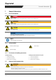
General Information 1 General Information 1.1 List of Information DANGER Imminent danger Failure to comply with this warning leads directly to death or to serious bodily harm. WARNING Potential danger Failure to comply with this warning leads directly to death or to serious bodily harm. CAUTION Hazard with low risk Non-compliance with the warning notice will result in slight to moderate bodily injuries.
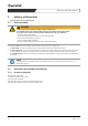
General Information 1.3 Using the Systemair-Cloud Confirming the Systemair-Cloud enables Systemair having access to your controller and its settings. It goes without saying that we do this only after request/permission of the unit user. Systemair-Cloud provides qualified support (malfunctions, incorrect settings, software errors etc.) in an easy and quick way which also saves costs and waiting time.
Important Safety Information 2 Important Safety Information 2.1 Safety Notes Observe the following safety instructions: • • • • • • • • Any work on the unit and first commissioning must be carried out by an expert technician. • For very cold external temperatures, a preheater for the heat pump (accessories) is needed to ensure operational reliability. Systemair offers the heater as an option and also incorporates it in the plan, so that it is possible to retrofit it if required.
Important Safety Information 2.2 Personnel 2.2.1 Personnel for Installation, Commissioning, Maintenance, Cleaning and Remedying Faults This instruction manual contains information about installation, commissioning, maintenance, cleaning and remedying faults. It is addressed to the expert technician. In order to ensure a proper function observe the following information: "" Carry out any work only according to the service manual.
Important Safety Information 2.4 Handing over to the Customer Handing over of the combi unit to the customer as follows: "" Describe the functions of the combi unit. "" Hand out all documentation for safe keeping. "" Instruct the customer with the help of the user manual. "" Indicate possible hazards. "" Point out maintenance and maintenance intervals. 2.
Delivery and Accessories 3 Delivery and Accessories "" Check the delivery for any possible damages. 3.1 Delivery Contents WARNING Danger of impacts and crushing due to falling or tipping ventilation unit! The ventilation module is only resting (not fixed in place) on top of the base and heat pump module. At a gradient of >30° from the vertical position, the ventilation unit can tip, slip and fall down. »» Secure the Genius against tipping! »» Do not tilt the Genius more than max.
Delivery and Accessories 3.2.2 Optional extra - Accessories Circulation system A hot water circulation is not recommended for energetic reasons. If a hot water circulation is necessary due to unfavourable ducting, it must be carried out according to the standards (see „13.2.3 Hot water generation“ page 102) Geothermal heat exchanger The temperature in the earth is almost constant throughout the year. Thus, the heat exchanger is suitable to pre-heat cold outdoor air in winter.
Description of the System 4 Description of the System The Combi Unit Genius realizes the complete building services for energy efficient buildings without water-based heating system. Modern buildings are planned with thicker envelopes. Thus, a mechanical ventilation is more and more necessary. New buildings as well as renovated buildings have higher insulation standards with less heating loads. Consequently, conventional heating systems are often over-dimensioned.
Description of the System 4.1.2 Controlled Residential Ventilation A controlled residential ventilation with heat recovery is integrated in the unit. It provides a balanced, pleasant indoor climate year-round, ensures constantly fresh air into the living rooms and transfers used air to the outside. At heat recovery, heat is transferred from the extract air to the supply air, thus remaining in the building.
Description of the System 4.3 Technical Data NOTE If larger houses/residential units (at a correspondingly lower heating load, e.g. for passive houses) are to be equipped with the Genius combi-unit, there is an option to use stronger fans to ensure the required air exchange. Please get in touch with Systemair early on in the planning phase). Genius Unit Data max. heating capacity kW 6 max.
Description of the System Genius Unit Cold water Data 1“ male Hot water 1“ male Circulation 3/4“ male Condensate hose connection 15 mm (5 pcs.) Safety valve 3/4“ male Outdoor air ventilation DN 160 Outdoor air heating pump DN 250 Extract air DN 160 Supply air DN 200 Secondary air DN 200 Exhaust air ventilation / heat pump DN 250 Other Refrigerant Filling quantity refrigerant Storage content Expansion tank Safety valve storage charging circuit Table 1: R410A kg 1.
Description of the System 4.4 Name Plate item no.: serial no.: date: Genius Complete Unit 36098 1304274 0 03.09.13 heating capacity max.: cooling capacity max: heat capacity part-load operation A2/L40: cold capacity part-load operation A30/L17: air flow max.: air flow max.(incl. sekundary air): Input power max.
Transport and Storage 5 Transport and Storage Systemair delivers the combi unit with the basic/hot water, heat pump and ventilation module as a complete unit. WARNING Impacts and crushing The ventilation module is not fixed to the base module with bolts. At a gradient of >30° from the vertical position, the ventilation unit can tip, slip and fall down. »» Do not tilt the unit more than max.
Assembly 6.2 Location Dimensions Figure 3: Minimum distances NOTE The indicated distances are minimum distances. "" Ensure the minimum distances for maintenance and service. 6.3 Preparation The Combi Unit Genius is very compact. The unit is placed on teflon sliders ensuring sound insulation and easy positioning. Adjustable feet are not used to avoid rocking due to balance point shifting. 6.3.1 Installation Place NOTE Ensure a professional noise reduction of the unit.
Assembly 6.4 Location 6.4.1 Disassembly Disassemble the modules only if the combi unit can not be transported as a complete unit to the installation place. The total height incl. pallet is approx. 2.20m. TIP Dismount previously the 4 side panels of the ventilation module. "" Remove the front and rear panel from the hinges. "" Unscrew the side panels from inside. Remove ventilation module The ventilation module is only placed on the basic / heat pump module and can slide out due to tilting.
Assembly 6.4.2 Assembly "" Follow the assembly steps at the installation place in reverse order of disassembly. 6.5 Connections 6.5.1 Hydraulic Connections Storage Tank All connections are lead through the rear side of the combi unit (ready-to-connect). The used electronic controlled high efficiency pump provides charging of the storage tank on demand. Remove panels The rear and right side panel are fixed to the unit and can not be removed.
Assembly Rear side connections Connections for hot and cold water as well as circulation and condensate drain are lead out through the rear side of the module (see fig. Figure 6).
Assembly 6.5.3 Air Ducts Heat Pump / Ventilation Unit Figure 7: 1 Ø 250 Heat pump outdoor air 2 Ø 250 Heat pump/exhaust air 3 Ø 160 Extract air 4 Ø 200 Supply air 5 Ø 200 Secondary air 6 Ø 160 Outdoor air 7 Combi grid (see "Facade Installation") Connection Storage Tank - Heat Pump Connections decoupling "" Decouple the following connections with flexible silencers: –– –– at the four upper ventilation connections, at the rear outlets of the heat pump.
Assembly 6.6 Electrical Connection WARNING Danger electrical voltage! »» The electrical connection is only permitted when carried out by trained electrician or trained and qualified personnel. »» The electrical connection should be done in accordance with the valid regulations. »» Prevent water from entering the electrical cabinet. »» Observe the 5 Security Rules! Connect the electrical connection and control cables NOTE "" Install a heating emergency switch to enable a complete shut-down of the unit.
Assembly 6.6.2 Connection Ventilation Module to Controller The connection of the ventilation module is done by three plug connectors. The plug connectors are located on the left side in the upper part of the basic module. They are already connected (see „6.4 Location“ page 19). The terminal assignment can be found in the wiring diagram (see appendix). 6.6.3 Room Controller The room controllers of the type RC-CDO are supplied as accessories and include a separate installation instructions.
Commissioning 7 Commissioning 7.1 First Commissioning NOTE Prevent dirt from entering the ducts and the unit. "" Do not commission the unit until all work has been completed. 7.1.1 Commissioning of the Heating during the cold Season Due to the limited heating capacity of the system, which is designed for the operation of a low-energy house, the building / residential unit must be heated during the cold season by the customer before the combi unit is taken into operation. 1. 2.
Commissioning Figure 9: 1 Air vent storage charging circuit 2 Fill and drain valve with ½“ hose connection Fill and vent storage charging circuit Fill and vent storage charging circuit Recommended unit pressure: 1.5 bar "" Unscrew the left cover of the heat pump module. "" Remove the cover forward. "" Activate the vent valve of the heat pump module (1). "" Connect the fill and drain valve (3) with a hose to the water network.
Commissioning 7.3 Internet Connection The controller is preconfigured for Internet access. It is connected to the TCP/IP interface with the router via a network cable. Subsequently, the router will automatically issue an IP address to the controller. This must be read out from the router settings. 7.3.1 Log on "" Start internet browser "" Enter the IP address to the command line. The log on screen will be displayed. "" Save the log on page to the favourites and rename it if required. 7.3.
Commissioning Sort rooms according to their relevance RECOMMENDATION Sort the room order according to the relevance, e.g.: Room 1 = Living room, Room 2 = Bedroom, Room 3 = Child room, …, Room 6 = Corridor, This order will be applied to all website pages. Thus, it is clearly arranged. The network connection is established after a moment. Enter addresses and room numbers NOTE Observe the correct order! 1. Enter the addresses. 2. Set the room number (factory setting: 0).
Commissioning 7.3.3.3 Fan Speed Settings The settings of the fan speed to balance the ventilation system by the website can be done in two ways: • • manually by Manual/Auto - current by the Settings - speed percentage. Fan speed settings with Manual/Auto (current) Supply air fan Status Manual Control output 5.0 V Extract air fan Status Manual Control output 5.0 V "" Reset the setting Manual in Manual/Auto back to Auto after the adjustment.
Commissioning 7.3.3.4 Setting the Maximum Power This function is only needed if, due to a very low heating/cooling load, the unit/duct network was not configured according to the maximum possible power/air quantity. In this case, the maximum speed of the secondary air fan and, automatically with it the maximum heating/cooling power (not the power for hot water production) must be limited: according to the specifications of the planer/the configuration by Systemair.
Maintenance / Remedying Faults 8 Maintenance / Remedying Faults 8.1 Alarm Status Faults are indicated and attributed on the page Alarm Status. The alarms are subdivided into different priority levels.
Maintenance / Remedying Faults 8.1.1 Alarm Types Alarm type Removal of the alarm cause Confirm Reset Automatic restart Class A Yes Yes Yes Yes Class B Yes Yes Yes Yes Class C Yes No Yes Yes A and B alarms will activate alarm outputs. Some B alarms do not influence the unit function (e.g. Filter Alarm). Class C alarms do not activate the alarm outputs. Class C alarms will be removed from the alarm list when the alarm input is reset also when not confirmed. 8.1.
Maintenance / Remedying Faults Remedy a fault: 1. Select the specific message 2. Click the symbol Confirm. The alarm must be confirmed manually to stop indicating it. Remedying faults: A , B and C alarms "" Fix the alarm or let it be fixed by a service technician. "" Select the alarm. "" Click the symbol Confirm. "" Select the sum alarm. "" Click the symbol Confirm. The alarm and the sum alarm must be confirmed manually one after another to stop indicating.
Maintenance / Remedying Faults 8.1.4.2 Inform Specialist Company WARNING Risk of property damage! A-alarms or faults that occur after confirmation repeatedly, indicate a default which can only be eliminated by a specialist company! »» Inform specialist company in both cases! 8.1.4.3 Description of the most important Alarms NOTE If the sum alarm heat pump triggers, one or more errors occur in the cooling circuit which are displayed in the following list.
Maintenance / Remedying Faults Remedying faults "" Fix the alarm or let it be fixed by a service technician. See chapter „9 Service“ for further information. "" Select the alarm. "" Click the symbol Confirm. or "" Block the alarm in the service level. WARNING Risk of injury and risk of damage to the combi unit! "" The blocking of alarms may only be carried out by service personnel NOTE Fault unremedied.
Maintenance / Remedying Faults Filter alarm: B-Alarm Meaning: Reset filter life value reached (see Settings). NOTE All functions of the combi unit remain active during this alarm. Remedying faults "" Change the filter. New filters can be obtained from Systemair. "" Reset filter life (see Settings). "" Select the alarm. "" Click the symbol Confirm. Communication error room: B-Alarm Meaning: Communication error between room controller and the corresponding room.
Maintenance / Remedying Faults 8.2 Ventilation Module 8.2.1 Filter Change and Wheel Cleaning WARNING Danger of injury from rotating fans! Rotating fans can cause very severe injuries. »» Disconnected the unit completely from the power supply before opening! NOTE Filters can not be cleaned. »» Change the filter a) if the filter life is reached, b) if the behaviour of the combi unit indicates a contaminated filter.
Maintenance / Remedying Faults 8.2.1.1 Change Filter (see „Figure 12: Change filter“) WARNING Danger of injury from rotating fans! Rotating fans can cause very severe injuries. »» Disconnected the unit completely from the power supply before opening! 99 Precondition: The combi unit is disconnected from the power supply. "" Open the shutter of the ventilation module. "" Pull out the filters 1, 2 and 3. "" Insert the new filter. NOTE Respect the air flow direction (arrow on the filter).
Maintenance / Remedying Faults Reset Filter Change and confirm. "" Reset filter life (see Settings). "" Select the alarm. "" Click the symbol Confirm. 8.3 Heat Pump Module A refrigerant circuit maintenance is not necessary. Due to weather-related influences, the evaporator fins must be checked from time to time. "" Check the evaporator depending on installation place and suction height of the working air (recommended once a year). "" Check the evaporator for contaminations (once a year).
Maintenance / Remedying Faults "" Unlock the two fasteners at the side panel. "" Remove the side panel. "" Check the condensate hoses for proper fixation and for dirt. Condensate hose cleaning "" Loosen the hose clamps on the heat pump module to remove clogged or heavily contaminated condensate hoses. "" Clean the condensate hoses. "" Attach the condensate hose with the hose clamps on the heat pump module. 8.4 Hot Water Module 8.4.
Maintenance / Remedying Faults WARNING Danger electrical voltage! »» The entire unit must be disconnected from the mains during check and replacement! »» Observe the 5 Security Rules! The condition of the sacrificial anode can be verified by a protective current measurement with an amperemeter. Procedure: "" Remove the front and the left panel to access to the storage tank. "" Lift the black tank cover "" Remove the black tank cover and the sealing. Access to the anode connection 1 ¼“.
Service 9 Service WARNING Danger electrical voltage! »» Let only qualified personnel carry out service work . »» The entire unit must be disconnected from the mains before service work! »» Observe the 5 Security Rules! 9.1 Ventilation Module 9.1.1 Rotor Alarm The rotor is out of function. No heat recovery. 9.1.1.1 Unit Characteristics in Winter The heat pump is still working. The setpoint is set automatically to an average room temperature of 19 °C. Change setpoint "" Change setpoint in Settings.
Service NOTE Observe the following during a replacement: Both fans have an alarm, even if only one is defective. 9.1.3 Sensors Defective sensors must be completely replaced. (Refer to the wiring diagram in the appendix and section „10.5 Alarm Status“ page 55.) 9.2 Heat Pump Module / Components The refrigerant circuit of the heat pump module is a closed system. It uses the security refrigerant R410a as heat transfer medium.
Service 9.2.1 High and Low Pressure Sensors Check / Change WARNING Danger electrical voltage! »» The entire unit must be disconnected from the mains before service work! »» Observe the 5 Security Rules! "" Disconnect the plug connection. "" Dismount the sensor bottom part. The sensor base is connected by means of a Schrader valve to the refrigeration system. It can be removed without draining the refrigerant circuit. 9.2.
Service 9.2.7 Sacrificial Anode To replace the sacrificial anode, the heat pump module must be removed and the water must be drained from the tank by one third. Pull out the heat pump module "" Loosen the two inlet and outlet nozzles on the rear side of the unit. "" Depressurize the connection pipes. "" Disconnect the two connections below the heat pump module. "" Disconnect the plug below the heat pump module on the left side. "" Disconnect the expansion valve plug connection on the board.
Service 9.3 Control 9.3.1 External Heat Pump Control In addition to these instructions, you can also download a technical manual from the Internet (www.systemair.com). This gives a description of the separate heat pump circuit board and its parameters. These parameters are factory set and can only be adjusted with an additional control unit. "" Inform the Systemair service or a Systemair service partner in case of an emergency service. 9.3.2 Central Building Services Unit Control 9.3.2.
Operation/Control via Internet/App 10 Operation/Control via Internet/App WARNING Damage due to operator error Operator errors could result in personal injury and/or property damage. »» Ensure that children never operate the unit unsupervised or play with it. »» Ensure that only persons have access which are capable of the appropriate use of the unit! NOTE Parameters which can be set are highlighted with blue letters. The formatting of the settings is done by the program. Examples: Enter 2.8.
Operation/Control via Internet/App 10.2 Access - Log on NOTE • All parameters can also be set by the display (see „11 Control via Display“ page 87). 10.2.1 Log on User Level "" Open the app on your smartphone or open the application on your PC. "" Enter "guest" in the field Password for user level. "" Select Save password. "" Click log on »» The Genius overview screen will be displayed. You are in the user level. 10.2.
Operation/Control via Internet/App 10.3.1 Overview The page Overview opens after log on. It shows the most important status of the control. Outdoor climate Outdoor temperature 19.6 %C Room control Room 1 Living room Status 1 Active Actual value temperature 21.5 °C Setpoint value temperature 21.0 °C Room 2 Bedroom Status 1 Active Actual value temperature 20.9 °C Setpoint value temperature 21.
Operation/Control via Internet/App 10.4 Actual Value / Setpoint The most important settings and reading out values. Genius Temperatures Room 1 3.8 °C Status Active Supply air temperature 37.0 °C PTC element blocked Extract air temperature 22.7 °C Actual value temperature 21.8 °C Hot water temperature 44.9 °C Setpoint value temperature 20.
Operation/Control via Internet/App Temperatures This field shows the actual temperature values of the different sensors. Temperatures Outdoor temperature 3.8 °C Supply air temperature 37.0 °C Extract air temperature 22.7 °C Hot water temperature 44.9 °C 10.4.1 Unit Unit Status Rotor operation Ventilation day-time operation normal Ventilation setback operation normal Actual ventilation stage normal Actual room temperature 20.6 °C Setpoint value temperature 20.6 °C 10.4.1.
Operation/Control via Internet/App Unit Status Hot water generation Ventilation day-time operation normal Ventilation setback operation Humidity protection Actual ventilation stage Minimal Actual room temperature normal Setpoint value temperature Party Setpoint supply air temperature Off Humidity protection Use the function Humidity protection only in case of longer absence (see Time program/Holiday).
Operation/Control via Internet/App 10.4.2 Hot Water Hot water Setpoint 45 °C Setpoint holiday 30 °C Fast charge hot water No Legionella mode No Emergency operation HW No Setpoint emergency operation 40 °C Hot water settings Setpoint Adjustment range: 30 °C ... 55 °C Default setting: 45 °C Setpoint holiday RECOMMENDATION: Keep the default settings. This will ensure a high performance coefficient of the heat pump.
Operation/Control via Internet/App Emergency operation You can maintain a reduced, temporary heating operation during a heat pump failure. The function can only be activated manually and during heat pump alarm to avoid operating errors. Settings: Yes / No Default setting: No Setpoint emergency operation Adjustment range: 18 °C ... 22 °C Default setting: 18 °C The emergency operation is fully functional even when the PTC function is switched off.
Operation/Control via Internet/App Settings room controller Settings: Active / Inactive Default setting: Active You can set the setpoint temperature of each room for a specific area. Depending on the heating mode you have selected, the unit setpoint is determined by these values (see Settings). The specific room controller copies the set value as well as it copies the new value to the website (according to the settings). Each room controller can be switched off manually (see section Room controller).
Operation/Control via Internet/App 10.6 Input/Output Genius Heat pump Analogue inputs Status On AE1, outdoor temperature 7.1 °C Heating/Cooling Heating AE2, supply air temperature 23.4 °C Capacity requirement 90 % AE 4, extract air temperature 22.0 °C Defrost Off UAE1, hot water temperature 44.6 °C Temp. air heat exchanger 21.1 °C UAE2, Supply air fan monitoring 10 V Temp. suction gas 21.6 °C UAE3, Extract air fan monitoring 10 V Cond. Temp. 22.
Operation/Control via Internet/App 10.6.2 Analogue Inputs The analogue inputs show the temperatures of the various sensors as well as the operating signal / mutual fan monitoring. Analogue inputs Temperature AE1 Outdoor temperature 7.1 °C AE2 Supply air temperature 23.4 °C AE4 Extract air temperature 22.0 °C UAE1 Hot water temperature 44.6 °C UAE2 Supply air fan monitoring 10 V UAE3 Extract air fan monitoring 10 V UAE4 Secondary air fan monitoring 10 V UA 2 ...
Operation/Control via Internet/App 10.6.4 Analogue Outputs The fans operate with 0 ... 10 V. The actual performance can be derived by these outputs. Example: 5 volts correspond 50 % power, 7 volts correspond 70 %. Analogue outputs AA1 Voltage Supply air fan control 6.0 V AA2 Extract air fan control 5.5 V AA3 Secondary air fan control 0.0 V AA4 preheater 0.0 V 10.6.5 Digital Outputs Actual components status (On/Off).
Operation/Control via Internet/App 10.7 Time Program Genius General Holiday Starting point End point Minute 28 Holiday 1 1 Jan 1 Jan Hour 11 Holiday 2 1 Jan 1 Jan Day 6 Holiday 3 1 Jan 1 Jan Month November Holiday 4 1 Jan 1 Jan Weekday Tuesday Holiday 5 1 Jan 1 Jan autom.
Operation/Control via Internet/App 10.7.2 Time Program 10.7.2.
Operation/Control via Internet/App 10.7.3 Holiday Program Holiday Starting point End point Holiday 1 2 Aug 21 Aug Holiday 2 1 Jan 1 Jan Holiday 3 1 Jan 1 Jan ... ... ... Holiday 21 1 Jan 1 Jan The unit capacity is reduced to a minimum during the set holiday times. Ventilation Humidity protection (min. air volume flow to protect the residential unit). Heating Average room temperature 18 °C, adjustable (frost protection, avoids cooling down of the residential unit, see Settings).
Operation/Control via Internet/App 10.8 Settings Genius Room temperature control Heating/Cooling Heat pump Auto ModBus address Cooling active when outdoor temp. > 26 °C Activate supply air rooms Heating active when outdoor temp. < 20 °C Number of rooms Cooling Modbus room address (ELA) Outdoortemp.comp. Heating Control mode Fixed setp.
Operation/Control via Internet/App Genius Extract air fan I-time 20 s Room designation Bedroom Speed at intense ventilation 70 % Speed at nominal ventilation 60 % Speed at reduced ventilation 35 % Room sensor internal Speed at hum. protect. ventilation... 15 % Setpoint room temperature 20.0 °C Speed at night cooling 85 % Temperature rise + 3 °C Room 3 Secondary air fan Temperature setback - 3 °C Parallel offset speed 100 % P-band 3 °C Min. speed 60 % I-time 20 s max.
Operation/Control via Internet/App Figure 25: Page Settings 2 10.8.1 Room Temperature Control Room temperature control Heating/Cooling Auto Cooling active when outdoor temp. > 26 °C Heating active when outdoor temp. < 20 °C Cooling Control mode Outdoortemp. managed Heating Control mode Fixed setp. Reference room 1 Setback operation room difference 0 °C Temperature holiday mode 18 °C Temperature rotor alarm 19 °C Control parameters Room controller Actual value 21.7 °C Setpoint 21.
Operation/Control via Internet/App 10.8.1.1 Operation Mode Heating/Cooling Auto Cooling active when outdoor temp. > Winter operation Heating active when outdoor temp. < Summer operation Heating/Cooling Cooling active when outdoor temp. > 26 °C Heating active when outdoor temp. < 20 °C Heating/Cooling Settings: Winter operation, Summer operation and Automatic Factory settings and recommendation: Auto(matic operation). Cooling active when outdoor temp. > 26 °C Heating active when outdoor temp.
Operation/Control via Internet/App Setpoint cooling curve Room setpoint at (32) 26 °C Room setpoint at (30) 25 °C Room setpoint at (28) 24 °C Room setpoint at (26) 23 °C Offset (-3 up to +3) 0 °C Setpoint value temperature 26 °C Offset value 0 °C Offset value -1 °C Setpoint value temperature 25 °C Room setpoint depending on outdoor temperature Room setpoint depending on actual outdoor temperature Start outdoor temp.
Operation/Control via Internet/App Heating: Type of the room temperature controlled control NOTE Average temperature as an actual value In some operating modes, the average room temperature of all active rooms is determined as actual value and compared with the setpoint (see Settings and Actual value / Setpoint, Setpoint Temperature).
Operation/Control via Internet/App Room setpoint depending on outdoor temperature A gradual increase of the setpoint temperature with decreasing outdoor temperature compensates the influence of the lower surface temperatures of room walls and windows to comfort. Setpoint heating curve Setpoint at (-15) 23 °C Setpoint at (-5) 22 °C Setpoint at (5) 21 °C Setpoint at (15) 20 °C Offset value -1 °C Offset (the temperature curve) Offset Adjustment range: -3 °C ...
Operation/Control via Internet/App Heating: Setpoint after rotor alarm Setpoint after rotor alarm Adjustment range: 18 °C ... 22 °C Default setting: 19 °C The passive heat recovery is deactivated after rotor alarm (see section 8.1). Thus, the efficiency of the combi unit is negatively affected. Therefore, the (average) room temperature setpoint is forced to reset during the alarm.
Operation/Control via Internet/App - Proportional band (P-Band), Integral time (I-Time) The room controller directly affects the supply air temperature controller. Figure 26: PID controller NOTE The PID controllers are preset and need normally no adjustment. Changes (if required) may only be carried out by qualified personnel. Control output: 50 %: no heating or cooling demand 50 ... 100 %: heating demand 0 ... 100 % 50 ... 0 %: cooling demand 0 ... 100 % - Heating: min. supply air temperature min.
Operation/Control via Internet/App Setting Manually Factory settings 40°C Heating ... ... Supply air type Control Manually Max. supply air temp. manually 40 °C Max. Supply air temperature Auto This parameter enables the user to set the maximum supply air temperature individually. The maximum supply air temperature must be increased step by step in winter (depending on outdoor temperature). Automatic setting max.
Operation/Control via Internet/App Speed Speed Supply air fan Speed at intense ventilation 70 °C Speed at nominal ventilation 50 °C Speed at reduced ventilation 35 °C Speed at hum. protect. ventilation. 15 °C Speed at night cooling 85 °C Extract air fan Speed at intense ventilation 70 °C Speed at nominal ventilation 50 °C Speed at reduced ventilation 35 °C Speed at hum. protect. ventilation. 15 °C Speed at night cooling 85 °C Secondary air fan Parallel offset speed 100 % Min.
Operation/Control via Internet/App Rotor settings Rotor Cooling recovery default value 2 °C Stop rotor default value 2 °C Defrost. level 3 add. frost protection On The rotating heat exchanger can have the following operating states: Heat recovery The rotor starts as soon as the room temperature drops below setpoint temperature.
Operation/Control via Internet/App 10.8.1.2 Hot Water Hot Water Start charge pump if HW temp. < S... 1 °C Stop charge pump if HW temp. > S... 2 °C Extended running pump 150 s Default value time program Automatic Start/Stop charge pump Start/Stop charge pump describes the hot water generation hysteresis. Default setting: 3 °C; i.e. with a default setting of the hot water temperature with 45 °C, the heat pump and the storage charge pump start at a temperature of 44 °C and end the generation at 47 °C.
Operation/Control via Internet/App PTC Adjustment range: 0 - 60 minutes Default setting: 45 minutes Electric heating elements (PTC elements "positive temperature coefficient") fulfil three functions: • • • Individual room temperature control, Emergency operation, peak load covering. A heat pump priority circuit ensures an optimized normal operation of the PTCs.
Operation/Control via Internet/App Activated night cooling Night cooling activated Setting: no settings required Default setting: 85 %, speed level for supply and extract air fan When night cooling is enabled, the speeds will automatically be increased during a fixed period of time (see Service, Settings). Thus, the air flow and the cooling capacity increases.
Operation/Control via Internet/App Sender name Systemair Re: Alarm Genius When this function is activated, an e-mail will be sent in the event of an alarm. NOTE To use this function, it may be necessary to make settings in the router. 10.8.1.
Operation/Control via Internet/App Define number of rooms Number of rooms 6 Room 1 1 ELA room address Room 2 2 3 ELA room address Room 3 4 5 ELA room address 6 Basic settings rooms Default settings rooms Room 1 Room sensor internal Window contact No NO/NC Setpoint room sensor NO 20.0 °C Temperature rise + 3 °C Temperature setback - 3 °C P-band 3 °C I-time 20 s Room designation Living room Room 2 Room sensor internal Window contact No NO/NC Setpoint room sensor NO 20.
Operation/Control via Internet/App Setpoint room temperature Setpoint room temperature 20.0 °C Temperature rise + 3 °C Temperature setback - 3 °C Use this setting to specify the minimum and maximum setpoints of each room. Factory settings: 20 °C / ±3 °C each. This means that the room temperature setpoint can be set below the Actual value/Setpoint and as well as at the room controller between 17 °C and 23 °C.
Operation/Control via Internet/App 10.9 Manual/Auto Heat pump Status Auto Control output 0% Supply air fan Status Auto Control output 0.0 V Extract air fan Status Auto Control output 0.0 V Secondary air fan Status Auto Control output 0.
Operation/Control via Internet/App 10.10 Chart Function "" Click on the chart link. This can be opened from all pages. »» The Chart page opens. The Chart function shows all status, temperatures etc. and saves them. Almost all temperatures, status, demands etc. can be recorded. Each recording is limited to 8 values per recording (time window). Figure 27: see Chart Signal Scale Last value Actual temperature left 25.0 °C Actual temperature left 24.1 °C Actual temperature left 24.
Operation/Control via Internet/App 10.10.1 Command Add signal Add signal Figure 28: Add signal Add signal: 1. Select a value in the Add signal window. 2. Decide whether the value should appear on the left or right scale. 3. Repeat 1 and 2 for all the values that you want to record. The recording starts. Adjust the vertical scale values: + / - and up / down buttons "" Reduce the highlighted scale by the + button. "" Increase the highlighted scale by the - button.
Operation/Control via Internet/App Figure 29: Display example Signal Scale Last value Status left 2 4-way valve left 0 Evaporator pressure left 9.7 bar Cond. pressure left 9.8 bar Actual Room Temperature Right 20.9 °C Deired Room Temperature Right 21.
Operation/Control via Internet/App Change properties "" Change the colour of the graph (Colour). "" Change the side of the display of the scale (left scale or right scale). "" Remove the signal with Remove. "" Confirm with OK. "" Close the window Properties with Cancel. You will see the change immediately in the chart being displayed. Figure 31: Properties 10.10.2 Command Remove all signals Remove all signals Remove all signals "" Click the symbol. "" Confirm the security query with Yes.
Operation/Control via Internet/App 10.10.4 Command Show sample marks Show sample marks Show sample marks "" Click the symbol. Figure 33: Sample marks shown Figure 34: Sample marks hidden Figure 36: Rulers shown Hide sample marks "" Click the symbol. 10.10.5 Command Hide/show ruler Show ruler Hide/show ruler "" Click the symbol. The ruler and the corresponding values will be displayed. Value at ruler (07:48:44) Figure 35: Values shown at the ruler Genius - V 1.
Operation/Control via Internet/App 10.10.6 Command Copy values to clipboard This feature allows exporting all recorded values to the clipboard. These can then be pasted to a table, for example in Word or Excel. Copy values to clipboard Define Time window (interval) "" Define the time window with the +/- and buttons. "" Click the symbol. The window Copy opens. Define resolution "" Select the desired resolution in the Copy window in the Pull-down menu.
Control via Display 11 Control via Display Control the unit via the website, as this is the comfortable way. You can also set all parameters via the display. The tree logic or hierarchy can be found in „11.5 Display Tree Logic“ page 89. 11.1 Display The display of the combi unit Genius provides 4x20 characters. It is background illuminated. The illumination is normally off. It is activated as soon as a button is pressed. The illumination will be turned off again after a period of inactivity.
Control via Display Parameters Change parameters in the service level: "" Move with the RIGHT, LEFT, UP and DOWN buttons to scroll through the menus until you reach the parameter you want to change. "" Push OK button. »» The cursor is positioned at the adjustable parameter. "" Increase or decrease the values with the up or down buttons. "" Push OK button. »» The new value is now confirmed.
Control via Display 11.5 Display Tree Logic Systemair Version Status: HW generation Version: 1.0-0-10 Speed: normal Id number: 11291470 12:11:20 13:21 Operation mode Heat pump mode Heating and Cooling Actual HP status: Heating Temp. setpoint Heat pump: Off Mode: Heating power 0% Ventilation mode Day: normal Night: normal Furnace operation: Off Manual cooling: No Manual cooling time: 60 min Room 1 Mode: Active PTC: blocked ... Genius - V 1.
Control via Display Temp. setpoint Ventilation Supply air temp. Act. value: 38.0 °C Setpoint: 38.2 °C Room temperature Act. value: 20.9 °C Setpoint: 21.0 °C Room 1 Room 1 ... Room temp.: 21°C Desired temp.: 21°C PTC heating: 0 % Room 2 Room 2 ... Room temp.: 21°C Desired temp.: 21°C PTC heating: 0 % ... Alarm event ... Hot Water Hot Water HW temp.: 46°C Desired temp. HW: 45°C HW temp.
Control via Display Alarm event 20 Nov 12:57 B Rotor alarm Service etc. Service Time/Date Date: 12:11:20 YY/MM/DD Time: 13:54 Weekday Tuesday Access Rights Settings Week program Running time Monday for 1: 00:00-24:00 for 2: 00:00-00:00 Week program HW Running time Tuesday for 1: 00:00-24:00 for 2: 00:00-00:00 etc.
Control via Display Holidays Holiday (MM:DD) 1: 01-01 - 01-01 2: 01-01 - 01-01 3: 01-01 - 01-01 Summer/Winter time ... Holiday (MM:DD) 19: 01-01 - 01-01 20: 01-01 - 01-01 21: 01-01 - 01-01 Summer/Winter time Automatic summer/ Summer/Winter time: Yes Service settings Supply air temperature Heating/cooling: Auto Cooling Outdoor temp. > 26 °C Heating Outdoor temp. < 20 °C Access Rights Heat pump Hot Water Cooling Mode setp. Cooling Mode setp.
Control via Display Service settings Supply air temperature Heat pump Hot Water Hot Water mode: Automatic Night cooling Night cooling active: No Filter change Outdoor temp. night Max.: 15.0 °C min.: 5.0 °C Room temp. min.: 20 °C Active when outdoor temp. 22°C Filter change Reset alarm time Filter alarm Reset alarm: No Set alarm time Filter life activation: 12 mon. Time since last change: 0 mon.
Control via Display Access Rights Log on Log on Enter password: **** Actual level: none Log off Log off No Actual level: none Change password Change password to level: None New password: **** Activate rooms: Service settings Access Rights Heat pump Heat pump: Modbus address = 1 Room designations Log on 1) Activate Rooms Enter password 1111 Number of rooms Room 1: 1 .. 10 Modbus address = 197 Language Room 2: Modbus address = 39 etc. After activation Config.
Control via Display Access Rights Log on Log on Enter password: **** Actual level: none Systemair Operation mode Log off Log off? No Actual level: none Systemair Change password Change password level: none New password: **** The following display settings/lines will be shown only after log on: Operation mode Manual/Auto Manual/Auto PTC room 1 (to 10) Auto Manual setpoint: 0.0 V Manual/Auto Supply air fan Auto Manual setpoint: 0.0 V Manual/Auto Extract air fan Auto Manual setpoint: 0.
Control via Display Service settings Supply air temperature Cooling Mode setp. Control parameters Room controller Heating Mode setp. P-band: 3°C Control parameters I-time: 20sec. Supply control: P-band: 70°C I-time: 30sec. Start hysteresis: Heat pump starts with a request > 30% Start hysteresis: 0.3°C Stop hysteresis: 0.3°C Start delay: 60sec. Stop delay:120sec Service settings Speed Supply air fan SAF intense: 70% SAF normal: 50% SAF reduced: 35% SAF humidity protect.
Control via Display Service settings Rotor Cooling recovery Start: 2.0°C Stop rotor at: 3.0°C Defrost. level: 3 Frost protection: On Service settings Hot Water mode: Automatic Start pump if: Temp. < Setpoint – 1°C Stop charge pump: Temp. > Setpoint + 2°C Service settings Extended running HW pump: 150 s 1) 1) Do not to change this value! PTC PTC function: On PTC start delay: 45 min . PTC defrost power HP: 20% Switch-off point: -20°C Preheater Setpoint: -10°C P-gain: 2.0 Genius - V 1.
Control via Display Service In-/Outputs Analogue inputs AI 1: xx°C AI 2: xx°C AI 3: xx°C AI 4: xx°C Digital inputs DI 1: EVU DI 2: Pressure monitoring DI 3: PV DI 4: Rotor Analogue outputs AO 1: Speed supply air fan Output: 5.0 V Status: Auto Man. Output: 0.0 V AO 2: Speed ETA Output: 5.0 V Status: Auto Man. Output: 0.0 V AO 3: Speed SEC Output: 5.0 V Status: Auto Man. Output: 0.0 V AO 4: Preheater Output: 0.0 V Status: Auto Man. Output: 0.
Room Controller 12 Room Controller 12.1 Description/Operation Detecting the room temperature and routing a request are the prior functions of room controllers. 1 1 On/Off button 2 UP button 3 DOWN button On/Off button "" 2 »» 3 The ON/OFF button deactivates the specific room. Consequence: The setpoint temperatures will change. The room will no longer be controlled individually. Depending on the settings, the temperature follows a different set value.
Comfort and Energy Efficiency 13 Comfort and Energy Efficiency 13.1 Utility Company Rates RECOMMENDATION Before unit installation, consult the utility company and the electrical installation company for your suitable rate. 13.1.1 Heat Pump Special Rate with Forced Interruption Most energy supply companies (utilities) offer special rates for heat pumps.
Comfort and Energy Efficiency Changing the heating curve NOTE The default settings ensure usually a comfortable operation with high energy efficiency. The temperature can be adjusted individually. Any reduction of the setpoint room temperatures by 1 °C leads to an energy saving of about 6%. However, you should never give up comfort. Therefore, a heating curve was stored as a default setting in Settings.
Comfort and Energy Efficiency An increase or decrease of the minimum value is only useful in exceptional cases. It may be necessary e.g. according to an unintended high solar entry, to reduce the supply air temperature over a certain time period to discharge the cooling load. Cooling recovery by the rotating heat exchanger The cooling recovery by the rotary heat exchanger can not to be compared to active cooling. The warm outdoor air is only pre-heated by the cooler extract air.
Comfort and Energy Efficiency NOTE One- and two-family houses are excluded from the applicable requirements to the construction and operation of drinking water installations. Relevant regulations according to the state of the art which describe effective prevention of legionella growth in drinking water installations, have only an advisory purpose for small systems. They are not made mandatory. Therefore, it is in the users discretion whether and how he uses them.
Declaration of Conformity 14 Declaration of Conformity Combi unit Genius Deutsch_Ende The manufacturer: Systemair GmbH Seehöfer Straße 45 D-97944 Windischbuch herewith declares that the following product: Description of the Products: Combi unit Indication: Genius Year of manufacture: 2016 all relevant regulations of the machinery directive 2006/42/EG Electromagnetic Compatibility Directive (EMV) (2014/30/EG).
Glossary 15 Glossary Setback operation Heat the rooms in setback operation during periods of absence or sleep. The periods can be defined by using the time program for room heating. The rooms will be heated with reduced room temperature during these periods. Alarm An alarm informs that the system has reported an error to the controller. Outdoor temperature compensated operation In the outdoor air compensated mode the setpoint room temperature is controlled depending on the outdoor temperature.
Appendix Terminal block ventilation module 122 Genius - V 1.
Article no. / date a Systemair GmbH • Seehöfer Str. 45 • D-97944 Windischbuch Tel.: +49 (0)7930/9272-0 • Fax: +49 (0)7930/9273-92 info@systemair.de • www.systemair.