
VEF WIRING DIAGRAM


Wiring Diagram
2 (2)
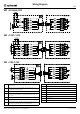
VEF + EC-Basic-CO2
VEF + F251–14 EC
VEF + 392–14 EC
L
Supply connection, power supply, phase, see nameplate for
voltage range
N
Supply connection, power supply, neutral conductor, see
nameplate for voltage range
PE
Ground connection
1
Not used.
Tach output, open collector, 1 pulse per revolution, max = 10
mA, SELV
2 (-)
Reference ground for control interface, SELV
3
0-10 V / PWM control input, Ri=100 kΩ, SELV
4 (+)
Fixed voltage output 10 VDC +/-3 %, max. 10 mA, short-
circuit-proof, power supply for ext. devices, SELV
BU
Blue
BN Brown
BK
Black
GND
Ground
RD
Red
YE
Yellow
WH
White
SC
Signal cable
FC
Fan cable
Systemair UAB Linų st. 101, LT–20174 Ukmergė, LITHUANIA
Phone: +370 340 60165 Fax: +370 340 60166 -en_GB- A005