
FC101 Programming Guide
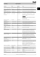

0-06 GridType
Option: Function:
[102] 200-240V/60Hz
[110] 380-440V/60Hz/IT-grid
[111] 380-440V/60Hz/Delta
[112] 380-440V/60Hz
[120] 440-480V/60Hz/IT-grid
[121] 440-480V/60Hz/Delta
[122] 440-480V/60Hz
[130] 525-600V/60Hz/IT-grid
[131] 525-600V/60Hz/Delta
[132] 525-600V/60Hz
0-07 Auto DC Braking
Option: Function:
Protective function against overvoltage at coast.
NOTICE
Can cause PWM when coasted.
[0] O This function is not active.
[1] * On This function is active.
3.1.2 0-1* Dene and Set-up Operations
A complete set of all parameters controlling the frequency
converter is called a set-up. The frequency converter
contains 2 set-ups: Set-up 1 and set-up 2. Furthermore, a
xed set of factory settings can be copied into 1 or both
set-ups.
Some of the advantages of having more than 1 set-up in
the frequency converter are:
•
Run the motor in 1 set-up (active set-up) while
updating parameters in another set-up (edit set-
up).
•
Connect the 2 motors (1 at a time) to the
frequency converter. Motor data for the 2 motors
can be placed in the 2 set-ups.
•
Rapidly change settings of the frequency
converter and/or the motor while the motor is
running. For example, ramp time or preset
references via bus or digital inputs.
The active set-up can be set as multi set-up, where the
active set-up is selected via input on a digital input
terminal and/or via the bus control word.
To copy set-up 1 to set-up 2, or copy set-up 2 to set-up 1,
use parameter 0-51 Set-up Copy. To avoid
conicting
settings of the same parameter within 2 dierent set-ups,
link the set-ups using parameter 0-12 Link Setups. Stop the
frequency converter before switching between set-ups
where parameters marked not changeable during operation
have dierent values.
Parameters that are not changeable during operation are
marked false in chapter 5 Parameter Lists.
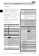
0-10 Active Set-up
Option: Function:
Select the set-up in which the frequency
converter operates.
[1] * Set-up 1 Set-up 1 is active.
[2] Set-up 2 Set-up 2 is active.
[9] Multi Set-
up
Used for remote set-up selections via digital
inputs and the serial communication port. This
set-up uses the settings from
parameter 0-12 Link Setups.
0-11 Programming Set-up
Option: Function:
The number of the set-up being edited is
shown in the LCP, ashing.
[1] Set-up 1 Edit set-up 1.
[2] Set-up 2 Edit set-up 2.
[9] * Active Set-up Edit parameters in the set-up selected via
digital I/Os.
0-12 Link Setups
Option: Function:
If the set-ups are not linked, a change between
them is not possible while the motor is running.
[0] Not
linked
When selecting a dierent set-up for operation,
the set-up change does not occur until the
motor is coasted.
[20] * Linked Copies not changeable during operation
parameters from 1 set-up to the other. It is
possible to switch set-ups while the motor is
running.
3.1.3 0-3* LCP Custom Readout and Display
Text
It is possible to customize the display elements for various
purposes.
Custom readout
The calculated value to be shown is based on settings in
parameter 0-30 Custom Readout Unit,
parameter 0-31 Custom Readout Min Value (linear only),
parameter 0-32 Custom Readout Max Value,
parameter 4-14 Motor Speed High Limit [Hz], and actual
speed.
Parameters Programming Guide
MG18B502 Danfoss A/S © 04/2018 All rights reserved. 27
3 3