
FC101 Programming Guide

3.15.6 22-8* Flow Compensation
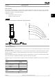
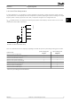
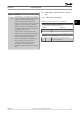
In certain applications, it is not possible for a pressure transducer to be placed at a remote point in the system, and it can
only be placed close to the fan/pump outlet. Flow compensation operates by adjusting the setpoint according to the output
frequency, which is almost proportional to ow. Thus, it compensates for higher losses at higher ow rates.
H
DESIGN
(required pressure) is the setpoint for closed-loop (PI) operation of the frequency converter and is set as for closed-
loop operation without ow compensation.
130BA383.11
Illustration 3.17 Flow Compensation Set-up
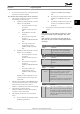
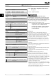
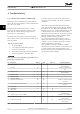
There are 2 methods which can be employed, depending on whether the speed at system design working point is known.
Parameter used
Speed at design point
KNOWN
Speed at design point
UNKNOWN
Parameter 22-80 Flow Compensation + +
Parameter 22-81 Square-linear Curve Approximation + +
Parameter 22-82 Work Point Calculation + +
Parameter 22-84 Speed at No-Flow [Hz] + +
Parameter 22-86 Speed at Design Point [Hz] + -
Parameter 22-87 Pressure at No-Flow Speed + +
Parameter 22-88 Pressure at Rated Speed - +
Parameter 22-89 Flow at Design Point - +
Parameter 22-90 Flow at Rated Speed - +
Table 3.12 Speed at Design Point Known/Unknown
Parameters Programming Guide
MG18B502 Danfoss A/S © 04/2018 All rights reserved. 93
3 3