
MA FRICO IHPA GB 190308
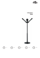


Infrapalm IHPA
5
GB
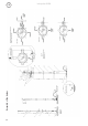
A: The cast-iron base
Lay the cast-iron base on a horizontal plane.
Screw the six leveling bolts (1) into the holes
in the base with the use of a hexagon socket
wrench. If the base is to be fixed to the
ground after assembly, use only three leveling
bolts interspersed with fixing bolts.
B: Attaching the steel tubes to the base
Screw steel tube (2) into the base and tighten.
(A steel bar is provided for this purpose.)
Slide the right-angled steel cable anchorage
(3) onto the steel tube ensuring the angle is
facing upwards. Do not add the plastic cable
gland (PG 13,5) at this stage. Screw on the
other two poles (4) and (5) and tighten.
C: Fitting the supply cable* Three phase**
Feed the supply cable (6) from the top to
the base until it exits by a few centimeters.
Dismantle the plastic cable gland and add
the inner nut to the supply cable and then
feed the cable through the hole of the steel
anchorage (3). Pull through until 50cm of
supply cable remains at the top.
Feed on the rubber seal to the cable, followed
by the main part of the cable gland and
locking nut. Assemble and tighten.
* On some versions, the feed cable and
junction box may already be connected. This
is for guidance only and should be dismantled
before attempting to install the cable.
** If monophase is required, consult with
your electrician.
D: Aluminum outer casing and heater and
cable casing
Fit the 900mm casing (7) with the earth cable
(8) attached to the base. Follow with ring (9),
700mm casing (10), ring (11), 525mm casing
(12), ring (13). Screw on flange (14) with
supplied key until the outer casing is locked
tightly into place. Add the heater support
frame (15) and screw it down tightly with one
of the two brass nuts (16).
Slide on the flange (17) followed by the
second brass nut (18), BUT DO NOT
TIGHTEN.
E: Heater and junction box installation
Carefully attach each heater (21) to the frame
with the supplied nuts and bolts, ensuring the
end of each heater arm is engaged under the
loose flange (17). The brass nut can now be
gradually tightened until the heater angles are
as required. Recommended angle 45°. Feed
the supply cable through the junction box
pole (19-20). Screw on ensuring the cable
does not twist.
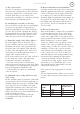
F: Electrical connections
This work should be completed by a qualified
electrician. Ensure there is no connection
to the electricity supply at this stage. Firstly
connect the supply cable to the junction box
(Fig A) neutral to the brass-colored connector
marked N phases to each steel phase
connector. (8kW models, two phases can be
added to the connector with the strongest
voltage rating.) earth to the central connector
ensuring a circuit to the outer steel frame
of the junction box and finally connecting
to the central steel post. Feed each heater
cable through the steel spring grommets into
the junction box, making the appropriate
connections. Finally check all electrical
connections are tight, replace and screw on
junction box cover. Install the globe cover
(22) and fix in place with washer (23) and
chrome-plated bolt (24).
Now connect to the appropriate electricity
supply.
The recommended three phase cross-section
of cables and power protections (fuse) for the
heater.
IHPA heaters
Total power
in kW
Fuse
Time-lag „C”
Cable cross
section in mm
2
(length up to 10
m)
4,0 10A 1,5
6,0 10A 1,5
8,0 10A 2,5