
Topvex FR03 11 Operating and maintenance 151626 (A002)


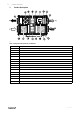
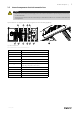
Table Of Contents
- 1 Warnings
- 2 Product description
- 3 Maintenance
- 3.1 Important
- 3.2 Maintenance intervals
- 3.3 Maintenance instructions
- 3.3.1 Changing supply/extract air filter
- 3.3.2 Checking the heat exchanger
- 3.3.3 Dismounting the heat exchanger block on ceiling mounted units
- 3.3.4 Checking the fans
- 3.3.5 Cleaning the extract louvres and inlet diffusers
- 3.3.6 Checking the outdoor air intake
- 3.3.7 Checking the duct system
- 3.3.8 Changing the internal battery
- 3.4 Troubleshooting
- 4 Service

Product description |
3
2.1 Description of internal components
2.1.1 Supply and extract air fans
The fans have external rotor motors of EC type which are steplessly controlled individually by setting the control signal
to a fixed value. It is possible to program the speed in 2 steps (normal/reduced) depending on the programming of the
week schedule. The motor bearings are life time lubricated and maintenance free. It is possible to remove the fans for
cleaning, see chapter 3 for more information.
2.1.2 Pressure sensor fans/filters
Two pressure sensors are installed (figure 1), each of the sensors has two functions. One function is to measure the dif-
ferential pressure over the inlet cone of the fan impellers to maintain the airflow at constant level (CAV function as
standard). The other function, is to measure the differential pressure over the supply and extract air filters so that when
the pressure drop reaches the set value, an alarm is triggered in the main regulator, which indicates that the filter needs
to be replaced.
2.1.3 Supply and extract air filters
The filters are of bag filter type with filter quality ePM1 60% (F7) for the supply air filter and ePM10 60% (M5) for the
extract air filter. The filters need to be replaced when polluted. New sets of filters can be acquired from your installer or
wholesaler.
2.1.4 Heat exchanger
Topvex FR models are equipped with a highly efficient, belt driven, rotating heat exchanger. Required supply air tem-
perature is therefore normally maintained without adding additional heat. The operation of the heat exchanger is auto-
matic and depends on the set temperature.
The heat exchanger is removable for cleaning and maintenance (chapter 3).
2.1.5 Rotor motor
The rotor motor drives the exchanger rotor with an infinitely rpm as long as there is a heat demand. The motor is con-
trolled by an analogue 0-10 V control signal (pos.6 figure 1.
2.1.6 Rotation guard
A sensor registers the rotation of the heat exchanger rotor. It’s connected to the main regulator which gives an alarm if
the rotor stops while there is a heat demand (pos. 12 figure 1.
151626 | A002