
Topvex FR03 11 Operating and maintenance 151626 (A002)

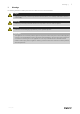
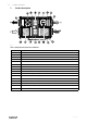
Table Of Contents
- 1 Warnings
- 2 Product description
- 3 Maintenance
- 3.1 Important
- 3.2 Maintenance intervals
- 3.3 Maintenance instructions
- 3.3.1 Changing supply/extract air filter
- 3.3.2 Checking the heat exchanger
- 3.3.3 Dismounting the heat exchanger block on ceiling mounted units
- 3.3.4 Checking the fans
- 3.3.5 Cleaning the extract louvres and inlet diffusers
- 3.3.6 Checking the outdoor air intake
- 3.3.7 Checking the duct system
- 3.3.8 Changing the internal battery
- 3.4 Troubleshooting
- 4 Service

Product description |
5
2.2 Internal components electrical connection box
Danger
• Make sure that the mains power supply to the unit is disconnected before performing any maintenance
or electrical work!
• All electrical connections must be carried out by an authorized installer and in accordance with local rules
and regulations.
Topvex FR03–11 are equipped with a built in regulator and internal wiring (figure 2).
Fig. 2 Electric components
Pos 10 shows location of TTC in FR03 and FR06-FR11
Position
Description
1
Control unit CU283W-4
2
Transformer 230/24V AC
3
Terminals for internal and external components
4
Terminals for internal wiring
5
Terminals for mains power supply to the unit
6
Contactor (K2) On/Off Pump control water (HW
units only, not present in EL-units)
7
Automatic fuse
8
Automatic fuse for heater
9
Contactor (K3) EL heater
10
TTC El heater control
11
Switch module
151626 | A002