Topvex FR03, FR06, FR08, FR11 Air Handling Unit Operation and Maintenance Instructions Document in original language | 151626 · A002 GB
© Copyright Systemair AB All rights reserved E&OE Systemair AB reserves the rights to alter their products without notice. This also applies to products already ordered, as long as it does not affect the previously agreed specifications.
Contents 1 2 3 4 Warnings.......................................................1 Product description..........................................2 2.1 Description of internal components ............3 2.1.1 Supply and extract air fans ........................................3 2.1.2 Pressure sensor fans/ filters.......................................3 2.1.3 Supply and extract air filters.......................................3 2.1.4 Heat exchanger .........................3 2.1.5 Rotor motor ...............
Warnings | 1 Warnings The following admonitions will be presented in the different sections of the document: Danger • Indicates a potentially or imminently hazardous situation which, if not avoided, could result in death or serious injury. Warning • Indicates a potentially hazardous situation that may result in minor or moderate injuries. Caution • Indicates a risk of damaging the product or prevent optimal operation.
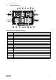
2 | Product description 2 Product description Fig.
Product description | 2.1 Description of internal components 2.1.1 Supply and extract air fans The fans have external rotor motors of EC type which are steplessly controlled individually by setting the control signal to a fixed value. It is possible to program the speed in 2 steps (normal/reduced) depending on the programming of the week schedule. The motor bearings are life time lubricated and maintenance free. It is possible to remove the fans for cleaning, see chapter 3 for more information. 2.1.
4 | Product description 2.1.7 Switch module A switch module with HMI and 2 TCP/IP connections is mounted in the heat recovery units (see figure 2). Note: 24V HMI connection dedicated for the display. The connection is only for HMI and no other connections is permitted. 2.1.8 Temperature sensor 4 temperature sensors (PT1000) are included in the unit from factory.
Product description | 2.2 Internal components electrical connection box Danger • Make sure that the mains power supply to the unit is disconnected before performing any maintenance or electrical work! • All electrical connections must be carried out by an authorized installer and in accordance with local rules and regulations. Topvex FR03–11 are equipped with a built in regulator and internal wiring (figure 2). Fig.
6 | Product description 2.3 Free cooling description This function is used during the warm period to save energy by using cold outdoor air, e.g. during night time, to cool down the building and thereby reducing the need for cooling during the day time. Note: The following is only valid if the free cooling function is activated in the program menu. Free cooling is only activated when the following starting conditions are met.
Maintenance | 3 Maintenance 3.1 Important Danger • Make sure that the mains power supply to the unit is disconnected before performing any maintenance or electrical work! • All electrical connections must be carried out by an authorized installer and in accordance with local rules and regulations. Warning • Although the mains power supply to the unit has been disconnected there is still risk for injury due to rotating parts that have not come to a complete standstill.
8 | Maintenance 3.3 3.3.1 Maintenance instructions Changing supply/extract air filter The bag filter cannot be cleaned and must be changed when necessary. New filters can be ordered from Systemair. Operation time between filter changes depends on the air pollution at the installation site. A differential pressure switch indicates when it’s time to change the filters. This will trigger an alarm in the control panel. When this occurs do the following: 1.
Maintenance | 3.3.2 Checking the heat exchanger After a long time of use dust may build up in the exchanger (pos. 5, figure 1) and block the airflow. It is important to clean the exchanger regularly to maintain high efficiency. The heat exchanger in the Topvex FR03–11 can be taken out of the unit. Wash in hot soapy water or use pressure air. Do not use detergent containing ammonia. Note: Make sure that the rotor motor is not exposed to moisture. 3.3.
10 | Maintenance 3.3.4 Checking the fans Even if the required maintenance, such as change of filters, is carried out dust and grease may slowly build up inside the fans (pos.1 and 2, figure 1 ). This will reduce the efficiency. The fans can be dismounted by loosening the 4 screws on the fan casing (figure 3). Topvex FR06–11 have a fan support bracket that needs to be removed by loosening 4 screws. The fans may be cleaned with a cloth or a soft brush. Do not use water.
Maintenance | 3.3.8 Changing the internal battery Note: This procedure requires knowledge of proper ESD protection; i.e. an earthed wristband must be used! When the alarm ”Internal Battery” is activated and the battery LED lights up red, the battery for backup of program memory and real-time clock has become too weak. The battery is replaced as described below. A backup capacitor saves the memory and keeps the clock running for at least 10 minutes after the power supply is removed.
12 | Maintenance 3.4 Troubleshooting Should problems occur, please check or correct the following before contacting your service representative. Always check if there are any alarms active in the control panel. 1. Fan(s) do not start • Check if there are any alarm messages • Check that the fuses are not defect (figure 2) • Check the settings in the control panel (times, week schedule, auto/manual operation etc.) 2.
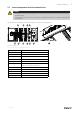
Service | 4 Service Before calling your service representative, make a note of the specification and production number from the type label (figure 4) 5 Ver. A Topvex XXXX 230/400V 25 A 4016 W 50Hz IP23 225kg 16kW 16kW Serial. no: 1234/567891-0001/140214 Systemair Sverige AB Industrivägen 3 SE-73930 Skinnskatteberg Sweden www.systemair.com 2 3 4 Fig.
14 | Service 151626 | A002
Service | 151626 | A002 15
Phone +46 222 440 00 Fax +46 222 440 99 www.systemair.