
Topvex FR03 11 Operating and maintenance 151626 (A002)


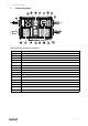
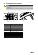
Table Of Contents
- 1 Warnings
- 2 Product description
- 3 Maintenance
- 3.1 Important
- 3.2 Maintenance intervals
- 3.3 Maintenance instructions
- 3.3.1 Changing supply/extract air filter
- 3.3.2 Checking the heat exchanger
- 3.3.3 Dismounting the heat exchanger block on ceiling mounted units
- 3.3.4 Checking the fans
- 3.3.5 Cleaning the extract louvres and inlet diffusers
- 3.3.6 Checking the outdoor air intake
- 3.3.7 Checking the duct system
- 3.3.8 Changing the internal battery
- 3.4 Troubleshooting
- 4 Service

4
| Product description
2.1.7 Switch module
A switch module with HMI and 2 TCP/IP connections is mounted in the heat recovery units (see figure 2).
Note:
24V HMI connection dedicated for the display. The connection is only for HMI and no other connections is
permitted.
2.1.8 Temperature sensor
4 temperature sensors (PT1000) are included in the unit from factory. The sensors are as follows:
• Supply air sensor
• Extract air temperature sensor
• Outdoor air temperature sensor
• Efficiency temperature sensor
The supply air sensor is loosely delivered with the unit and needs to be installed in the supply air duct externally from
the unit. See Installation instructions for more information.
2.1.9 Water heating battery
In units with built in water heating battery the hot water coil is located next to the supply air connection. The hot water
coil can be either HWL (hot water coil, low power) or HWH (hot water coil, high power). The coil material is copper pip-
ing with a frame of galvanized sheet steel and aluminium fins. The coil is equipped with venting and immersion sensor
for frost protection.
2.1.10 Electrical heater
In units with built in electrical heater the heating rods are located after the supply air fan in the airflow direction. The
material is stainless steel. The electrical heating battery has both automatic and manual overheating protection. The
manual overheat protection is reset by pushing the red button on top of the electrical heater frame (pos. 8 figure 1).
The power demand of the electric heating coil is controlled by the main regulator, which controls the heat steplessly by
a TTC triac control according to the desired supply/extract or room air temperature that is set in the control panel.
Danger
• Make sure that the mains power supply to the unit is disconnected before performing any maintenance
or electrical work!
• All electrical connections must be carried out by an authorized installer and in accordance with local rules
and regulations.
151626 | A002