Topvex FR03, FR06, FR08, FR11 Air Handling Unit Installation instructions Document in original language | 151625 · A005 GB
© Copyright Systemair AB All rights reserved E&OE Systemair AB reserves the rights to alter their products without notice. This also applies to products already ordered, as long as it does not affect the previously agreed specifications.
Contents 1 2 3 4 5 EU Declaration of Conformity .............................1 UK Declaration of Conformity .............................2 Warnings.......................................................3 Product information .........................................3 4.1 General ................................................3 4.2 Technical data .......................................4 4.2.1 Dimensions ...............................4 4.2.2 Weights ...................................5 4.2.
EU Declaration of Conformity | 1 EU Declaration of Conformity Manufacturer Systemair Sverige AB Industrivägen 3 SE-739 30 Skinnskatteberg Sweden Phone: +46 222 440 00 www.systemair.com The manufacturer hereby confirms that Topvex FR03–11 comply with all applicable requirements in the following directives and regulations.
2 | UK Declaration of Conformity 2 UK Declaration of Conformity Manufacturer Systemair Sverige AB Industrivägen 3 SE-739 30 Skinnskatteberg Sweden Phone: +46 222 440 00 www.systemair.com The manufacturer hereby confirms that Topvex FR03–11 comply with all applicable requirements in the following directives and regulations.
Warnings | 3 Warnings The following admonitions will be presented in the different sections of the document: Danger • Indicates a potentially or imminently hazardous situation which, if not avoided, could result in death or serious injury. Warning • Indicates a potentially hazardous situation that may result in minor or moderate injuries. Caution • Indicates a risk of damaging the product or prevent optimal operation.
4 | Product information 4.2 Technical data 4.2.
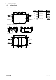
Product information | Description Position X X Y Supply air B Exhaust air C Outdoor air D Extract air G L/2 A Symbol D H H M C A G I B L/2 L Bottom side, right hand unit A J E K 3 E 2 U P F N C S N R Q øD B W W T Right hand unit L I G L/2 A H M H B D G I C L/2 X X Y Operating side, right hand unit Table 1 Dimensions Model A B C D E F G H I J K L FR03 1720 1115 540 ø315 60 270 275 450 275 1145 590 1502 FR06 2160 1315 640 ø40
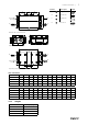
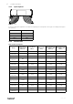
6 | Product information 4.2.3 Space required Fig. 1 Space required In case the sliding door application is installed the required space corresponds to the height of the sliding door support bars (50 mm). 4.2.4 Model W (mm) FR03 576 FR06 763 FR08 807 FR11 844 Electrical data Table 2 Power Consumption Model Fans (W tot.) 230V 1~ and 400 V 3N~ Fans (W tot.) 230V 3~ El Heating battery (kW tot.
Product information | 4.3 Transport and storage The Topvex FR03–11 should be stored and transported in such a way that it is protected against physical damage that can harm panels, handles, display etc. It should be covered so that dust, rain and snow cannot enter and damage the unit and its components. The appliance is delivered in one piece containing all necessary components, wrapped in plastic on a pallet for easy transportation.
8 | Installation 5 Installation 5.1 Unpacking Topvex FR03–11 are delivered on a pallet (figure 2 and figure 3). Necessary components like handles and supply air temperature sensor are placed inside the unit. The inspection hatches are opened by the use of a 16 mm cap key (figure 4). To facilitate opening and closing of the inspection hatches apply the 8 handles that are placed inside the unit on delivery.
Installation | 5.3 Installing the unit The unit can be installed in the following positions Fig. 5 Possible installation positions Position Description A Installation flat on the ground. Left and right connections are possible. B Ceiling installation. Left and right connections are possible. C Vertical wall installation with the supply air upward. D Horizontal wall installation Left and right connections are possible.
10 | Installation 4 Install the unit by the use of the mounting brackets fitted on the unit on delivery. Note: If the unit is installed in the ceiling or on the wall assure that the unit is pressed tightly to the mounting surface before fastening the mounting brackets. Make sure to use proper fastening device (screw/bolts) considering the weight of the unit and the type of surface it is fitted to. The installation can only be performed by an authorized installer.
Installation | 5.4 Supply air sensor The supply air sensor is enclosed in the unit package on delivery. Mount the supply air sensor the supply air duct 3 m after the air handling unit (figure 7). Connect the sensor to terminal 30–31 (chapter 5.6.6) in the electrical connection box. Other temperature sensors are built in to the unit from factory. Fig. 7 Installed supply air sensor 5.
12 | Installation 4 Mount the wheels Mount the wheels in the prepared threaded inserts on the side of the inspection hatch with the enclosed screws and washers. 5 Sliding door support rails Mount the sliding door rails on each side of the unit. Fasten it to the casing with screws in the prepared threaded inserts. 6 Fasten with BSS screws Fasten the rail to the side of the casing with the enclosed BSS screws.
Installation | 7 Open hatch Open the hatch by unlocking the 2 inner handles (pos. 1) followed by the 2 outer handles (pos. 2). The hatch can now be pushed toward the centre of the unit. Only one hatch at the time can be opened like this. 8 Apply seal Apply the enclosed self adhesive seal strip to the inner frame of the unit casing. 9 Close hatch Close the hatch with the 4 handles. Make sure the hatch closes properly. Repeat the procedure from step 7 on the other hatch.
14 | Installation 5.6 Connections 5.6.1 Ducting Fig. 8 Air direction, left hand unit Fig.
Installation | 5.6.2 Condensation and heat insulation Outdoor air duct and exhaust ducts must always be well insulated against condensation. Correct insulation installation on ducts connected to the unit is especially important. All ducts installed in cold rooms/areas must be well insulated. Use insulating covering (minimum 100 mm mineral wool) with plastic diffusion barrier. In areas with extremely low outdoor temperatures during the winter, additional insulation must be installed.
16 | Installation 5.6.5 Electrical connections, components Topvex FR03–11 are equipped with a built in regulator and internal wiring (figure 11). Fig.
Installation | 5.6.6 External connections Table 4 Connections to external functions Description Terminal block PE Ground N N Earthed neutral (mains power supply) Used for phase 230V 1~ and 400V 3~ L1 L1 Phase (mains power supply) Used for phase 230V 1~ if the unit has this mains 400V 3~/230V 3~ L2 L2 Phase (mains power supply) 400V 3~/230V 3~ L3 L3 Phase (mains power supply) 400V 3~/230V 3~ 1 G Auxiliary supply (Pressure transmitter.
18 | Installation 5.6.7 BMS Connection Communication possibilities for control unit. • RS485(Modbus): 50-51-52 or 60-61-62 • RS485(BACnet): 50-51-52 or 60-61-62 • RS485(Exoline): 50-51-52-53 or 60-61-62-63 • TCP/IP Exoline • TCP/IP Modbus • TCP/IP WEB • TCP/IP BACnet RS 485 connection Fig. 12 TCP/IP connection Connect the device to panel outlet or switch module, depending on type of air handling unit. Fig.
Installation | 5.7 Installing NaviPad control panel The protection class of the NaviPad control panel is IP 54 and 0-50° permitted ambient temperature. If NaviPad is mounted outdoor the panel needs to be protected against direct UV radiation. Communication between the panel and the controller in the cabinet is possible with up to 100 meters of cable. 5.7.1 Dimensions NaviPad NaviPad is the control panel for Systemair's air handling units and contains several selectable languages.
20 | Installation 5.7.2 Mounting control panel The NaviPad control panel with 3 m cable and holder are enclosed with the air handling unit. Self drilling screws are enclosed at delivery for mounting of the panel holder on the air handling. For mounting to a wall use suitable fastenings screws depending on the surface. NaviPad is connected to the switch module in the air handling unit at delivery. See enclosed Quick guide for operating of the control panel. Fig. 14 Installation on unit or on wall 5.
151625 | A005
Phone +46 222 440 00 www.systemair.