Topvex FC Compact Air Handling Unit Installation instructions Document in original language | 151627 · A004 GB
© Copyright Systemair AB All rights reserved E&OE Systemair AB reserves the rights to alter their products without notice. This also applies to products already ordered, as long as it does not affect the previously agreed specifications.
Contents 1 2 3 4 5 EU Declaration of Conformity .............................1 UK Declaration of Conformity .............................2 Warnings.......................................................3 Product information .........................................3 4.1 General ................................................3 4.2 Technical data .......................................4 4.2.1 Dimensions and weight ...............4 4.2.2 Space required...........................5 4.2.
EU Declaration of Conformity | 1 EU Declaration of Conformity Manufacturer Systemair Sverige AB Industrivägen 3 SE-739 30 Skinnskatteberg Sweden Phone: +46 222 440 00 www.systemair.com The manufacturer hereby confirms that Topvex FC comply with all applicable requirements in the following directives and regulations.
2 | UK Declaration of Conformity 2 UK Declaration of Conformity Manufacturer Systemair Sverige AB Industrivägen 3 SE-739 30 Skinnskatteberg Sweden Phone: +46 222 440 00 www.systemair.com The manufacturer hereby confirms that Topvex FC comply with all applicable requirements in the following directives and regulations.
Warnings | 3 Warnings The following admonitions will be presented in the different sections of the document: Danger • Indicates a potentially or imminently hazardous situation which, if not avoided, could result in death or serious injury. Warning • Indicates a potentially hazardous situation that may result in minor or moderate injuries. Caution • Indicates a risk of damaging the product or prevent optimal operation.
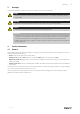
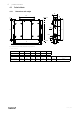
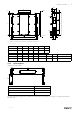
4 | Product information 4.2 4.2.1 Technical data Dimensions and weight M 148 J D I 70 A-A F H E A øK 70 137 G *1/2" 60 98 A-A C B 98 L 60 A-A Fig.
Product information | M D 148 J 70 A-A I F H E A □K 70 C C 60 100 A-A B G 136 *1/2" 100 L 60 A-A Fig. 2 Dimensions Topvex FC04, Topvex FC06 (mm) drawn as right hand unit * = male connection A B C D E F Topvex FC04 2024 2561 1190 1204 2098 2242 Topvex FC06 2214 2546 1182 1208 2288 2432 G H I J □K L M Weight, kg Topvex FC04 446 979 600 200 250x500 200 400 420 Topvex FC06 471 1073 671 250 300x600 300 500 510 Model Model 4.2.
6 | Product information 4.2.3 Electrical data Topvex FC Model Fans (W tot.) 230V 1~ and 400 V 3N~ El Heating battery (kW tot.) Fuse (mains) (A) for 230 V 1~ and 400 V 3~ Topvex FC02 EL 1040 5 3x13 Topvex FC02 None, HWL, HWH 1040 - 10 Topvex FC04 EL 1536 10 3x25 Topvex FC04 None, HWL, HWH 1536 - 10 Topvex FC06 EL 5134 16 3x35 Topvex FC06 None, HWL, HWH 5134 - 3x10 4.
Installation | Note: Necessary parts like control panel, supply air sensor, handles, drainage pipe with drain trap are placed loosely inside the unit. The unit must not be put into operation before the enclosed parts are removed and installed properly. Warning The unit is heavy. Be careful during transport and mounting. Risk of injury through pinching. Use protective clothing. Be careful so the unit don't tip over. 5 Installation Topvex FC is designed for ceiling installation.
8 | Installation 5.3 Condensation drain The unit must be connected to the condensation drain. A transition, tube and drain trap are enclosed upon delivery. Connect the drainage on the units exhaust side (pos 2, figure 4). The drainage on the supply side (pos 1) must be connected if the unit will be used with cooling equipment or if it will run extensively where the outdoor climate is very humid. On left hand units the positions of the connection are reversed.
Installation | G½" 2 Fig. 4 Drainage connection, right hand unit Table 1 H (mm) Max.
10 | Installation 5.4 Installing the unit The units are designed for ceiling installation. Left and right connections are possible. Fig. 5 Installing position, left hand unit Fig.
Installation | 5.4.1 Installation procedure Warning Beware of sharp edges during mounting and maintenance. Make sure that a proper lifting device is used. Use protective clothing. Warning The units electrical connection to the mains power supply must be preceded by an all pole circuit breaker with a minimum 3 mm gap.
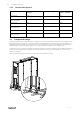
12 | Installation 5.6 Mounting the sliding door kit A sliding door kit for the inspection doors can be acquired as an accessory and can be mounted on the units. The kit is installed according to below procedure. Warning The door handles are only intended to be used during the installation and service. Handles must be removed before the unit is put into operation to ensure the required level of safety for the unit.
Installation | 5 Fasten with BSS screws Fasten the rail to the side of the casing with the enclosed BSS screws. 6 Open hatch Open the hatch by unlocking the inner handles (pos. 1) followed by the outer handles (pos. 2). The hatch can now be pushed toward the centre of the unit. Only one hatch at the time can be opened like this. 7 Apply seal Apply the enclosed self adhesive seal strip to the inner frame of the unit casing. 8 Close hatch Close the hatch with the handles.
14 | Installation 5.7 Connections 5.7.1 Ducting Fig.
Installation | 5.7.2 Condensation and heat insulation Outdoor air duct and exhaust ducts must always be well insulated against condensation. Correct insulation installation on ducts connected to the unit is especially important. All ducts installed in cold rooms/areas must be well insulated. Use insulating covering (minimum 100 mm mineral wool) with plastic diffusion barrier. In areas with extremely low outdoor temperatures during the winter, additional insulation must be installed.
16 | Installation Fig. 9 Topvex FC is equipped with a built in regulator and internal wiring (figure 10). Fig.
Installation | 5.7.5 External connections Table 3 Connections to external functions Description Terminal block PE Ground N N Earthed neutral (mains power supply) Used for phase 230V 1~ and 400V 3~ L1 L1 Phase (mains power supply) Used for phase 230V 1~ if the unit has this mains 400V 3~/230V 3~ L2 L2 Phase (mains power supply) 400V 3~/230V 3~ L3 L3 Phase (mains power supply) 400V 3~/230V 3~ 1 G Auxiliary supply (Pressure transmitter.
18 | Installation 5.7.6 BMS Connection Communication possibilities for control unit. • RS485(Modbus): 50-51-52 or 60-61-62 • RS485(BACnet): 50-51-52 or 60-61-62 • RS485(Exoline): 50-51-52-53 or 60-61-62-63 • TCP/IP Exoline • TCP/IP Modbus • TCP/IP WEB • TCP/IP BACnet RS 485 connection Fig. 11 TCP/IP connection Connect the device to panel outlet or switch module, depending on type of air handling unit. Fig.
Installation | 5.8 Installing NaviPad control panel The protection class of the NaviPad control panel is IP 54 and 0-50° permitted ambient temperature. If NaviPad is mounted outdoor the panel needs to be protected against direct UV radiation. Communication between the panel and the controller in the cabinet is possible with up to 100 meters of cable. 5.8.1 Dimensions NaviPad NaviPad is the control panel for Systemair's air handling units and contains several selectable languages.
20 | Installation 5.9 Additional equipment For information concerning additional external equipment such as valve actuators, motorized dampers, roof units, wall grilles etc. see technical catalogue and their enclosed instructions. For electrical connections of external components see enclosed wiring chart.
151627 | A004
Phone +46 222 440 00 www.systemair.