Topvex FC Air Handling Unit Operation and Maintenance Instructions Document in original language | 151628 · A002 GB
© Copyright Systemair AB All rights reserved E&OE Systemair AB reserves the rights to alter their products without notice. This also applies to products already ordered, as long as it does not affect the previously agreed specifications.
Contents 1 2 3 4 Warnings.......................................................1 Product description..........................................2 2.1 Internal components ...............................2 2.2 Description of internal components ............3 2.2.1 Supply and extract air fans ........................................3 2.2.2 Supply and extract air filters.......................................3 2.2.3 Pressure sensor fans/ filters.......................................3 2.2.4 Heat exchanger ....
Warnings | 1 Warnings The following admonitions will be presented in the different sections of the document: Danger • Indicates a potentially or imminently hazardous situation which, if not avoided, could result in death or serious injury. Warning • Indicates a potentially hazardous situation that may result in minor or moderate injuries. Caution • Indicates a risk of damaging the product or prevent optimal operation.
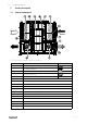
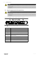
2 | Product description 2 Product description 2.1 Internal components Fig.
Product description | 2.2 Description of internal components 2.2.1 Supply and extract air fans The fans have external rotor motors of EC type which are steplessly controlled individually by setting the control signal to a fixed value. It is possible to program the speed in 2 steps (normal/reduced) depending on the programming of the week schedule. The motor bearings are life time lubricated and maintenance free. It is possible to remove the fans for cleaning, see chapter 4 for more information. 2.2.
4 | Product description Danger • Make sure that the mains power supply to the unit is disconnected before performing any maintenance or electrical work! • All electrical connections must be carried out by an authorized installer and in accordance with local rules and regulations. 2.
Defrost function | 2.4 Free cooling description This function is used during the warm period to save energy by using cold outdoor air, e.g. during night time, to cool down the building and thereby reducing the need for cooling during the day time. Note: The following is only valid if the free cooling function is activated in the program menu. Free cooling is only activated when the following starting conditions are met.
6 | Maintenance Warning • Although the mains power supply to the unit has been disconnected there is still risk for injury due to rotating parts that have not come to a complete standstill. • Beware of sharp edges during mounting and maintenance. Use protective clothing. 4.2 Maintenance intervals The table below shows recommended maintenance intervals for the unit and the installation.
Maintenance | 4.3 Maintenance instructions 4.3.1 Open the doors The doors are secured with safety wire connection to ensure that the doors don’t fall downwards with force (figure 4). Open the door using the enclosed handles, push back the door to be able to unhook the two carabiners. Lower the door carefully. The middle hatch is opened by unscrewing 4 screws (figure 5.) Fig. 3 Note: Attach the safety wire again when maintenance is finished.
8 | Maintenance 4.3.2 Changing supply/extract air filter The bag filter cannot be cleaned and must be changed when necessary. New filters can be ordered from Systemair. Operation time between filter changes depends on the air pollution at the installation site. A differential pressure switch indicates when it’s time to change the filters. This will trigger an alarm in the control panel. When this occurs do the following: 1. Replace the filters with new ones as described below. 2.
Maintenance | 4.3.3 Checking the heat exchanger After a long time of use dust may build up in the exchanger and block the airflow. It is important to clean the exchanger regularly (once a year) to maintain high efficiency. The heat exchanger can be taken out of the unit for maintenance (figure 5). Danger • Risk of personal injury! The heat exchanger is heavy. There is a risk that the heat exchanger falls out of the unit.
10 | Maintenance 4.3.4 Checking the fans Even if the required maintenance, such as change of filters is carried out, dust and grease may slowly build up inside the fans. This will reduce the efficiency. The fans are easily taken out from the unit (figure 6) by loosening 4 screws and disconnecting the fast couplings to the electric wires. Depending on the accessories installed, remove the tubing next to the fast couplings for the extract air fan or both the extract air fan and supply air fan.
Maintenance | 4.3.9 Checking the duct system Dust and grease settlements may build up in the duct system even if filters are changed regularly. This will reduce the efficiency of the installation. The ducts should therefore be cleaned/changed when necessary. Steel ducts can be cleaned by pulling a brush, soaked in hot soapy water through the duct via diffuser/louvre openings or special inspection hatches in the duct system (if fitted). 4.3.
12 | Troubleshooting 5 Troubleshooting Should problems occur, please check or correct the following before contacting your service representative. Always check if there are any alarms active in the control panel. 1. Fan(s) do not start • Check if there are any alarm messages • Check that the fuses are not defect (figure 2) • Check the settings in the control panel (times, week schedule, auto/manual operation etc.) 2.
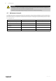
Service | 6 Service Before calling your service representative, make a note of the specification and production number from the type label (figure 7) 5 Ver. A Topvex XXXX 230/400V 25 A 4016 W 50Hz IP23 225kg 16kW 16kW Serial. no: 1234/567891-0001/140214 Systemair Sverige AB Industrivägen 3 SE-73930 Skinnskatteberg Sweden www.systemair.com 2 3 4 Fig.
14 | Service 151628 | A002
Service | 151628 | A002 15
Phone +46 222 440 00 Fax +46 222 440 99 www.systemair.