
TOPVEX FC OPERATING MAINTENANCE 151628A002


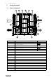
Table Of Contents
- 1 Warnings
- 2 Product description
- 3 Defrost function
- 4 Maintenance
- 4.1 Important
- 4.2 Maintenance intervals
- 4.3 Maintenance instructions
- 4.3.1 Open the doors
- 4.3.2 Changing supply/extract air filter
- 4.3.3 Checking the heat exchanger
- 4.3.4 Checking the fans
- 4.3.5 Checking the hot water heating battery
- 4.3.6 Checking the electrical heating battery
- 4.3.7 Cleaning the extract louvres and inlet diffusers
- 4.3.8 Checking the outdoor air intake
- 4.3.9 Checking the duct system
- 4.3.10 Changing the internal battery
- 5 Troubleshooting
- 6 Service

Product description |
3
2.2 Description of internal components
2.2.1 Supply and extract air fans
The fans have external rotor motors of EC type which are steplessly controlled individually by setting the control signal
to a fixed value. It is possible to program the speed in 2 steps (normal/reduced) depending on the programming of the
week schedule. The motor bearings are life time lubricated and maintenance free. It is possible to remove the fans for
cleaning, see chapter 4 for more information.
2.2.2 Supply and extract air filters
The filters are of bag filter type with filter quality ePM1 60% (F7) for the supply air filter and ePM10 60% (M5) for the
extract air filter. The filters need to be replaced when polluted. New sets of filters can be acquired from your installer or
wholesaler.
2.2.3 Pressure sensor fans/filters
Two pressure sensors are installed (figure 1), each of the sensors has two functions. One function is to measure the dif-
ferential pressure over the inlet cone of the fan impellers to maintain the airflow at constant level (CAV function as
standard). The other function, is to measure the differential pressure over the supply and extract air filters so that when
the pressure drop reaches the set value, an alarm is triggered in the main regulator, which indicates that the filter needs
to be replaced.
2.2.4 Heat exchanger
Topvex FC models are equipped with a counter flow heat exchanger and a by-pass damper. The operation of the by-
pass damper is automatic and depends on the set temperature or if deicing is in operation.
The heat exchanger is removable for cleaning and maintenance, see chapter 4 for more information.
For defrosting a pressure transmitter is installed which measure the differential pressure over the heat exchanger.
2.2.5 Switch module
A switch module with HMI and 2 TCP/IP connections is mounted in the heat recovery units (see figure 2).
Note:
24V HMI connection dedicated for the display. The connection is only for HMI and no other connections is
permitted.
2.2.6 Temperature sensor
4 temperature sensors (PT1000) are included in the unit from factory. The sensors are as follows:
• Supply air sensor
• Extract air temperature sensor
• Outdoor air temperature sensor
• Efficiency temperature sensor
The supply air sensor is loosely delivered with the unit and needs to be installed in the supply air duct externally from
the unit. See Installation instructions for more information.
2.2.7 Water heating battery
In units with built in water heating battery the hot water coil is located next to the supply air connection. The hot water
coil can be either HWL (hot water coil, low power) or HWH (hot water coil, high power). The coil material is copper pip-
ing with a frame of galvanized sheet steel and aluminium fins. The coil is equipped with venting and immersion sensor
for frost protection.
2.2.8 Electrical heater
In units with built in electrical heater the heating rods are located after the supply air fan in the airflow direction. The
material is stainless steel. The electrical heating battery has both automatic and manual overheating protection. The
manual overheat protection is reset by pushing the red button on top of the electrical heater frame (pos. 11 figure 1).
The power demand of the electric heating coil is controlled by the main regulator, which controls the heat steplessly by
a TTC triac control according to the selected control function that is set in the control panel.
151628 | A002