EC - Controller Invento IFT Drives Operating and Installation instructions
Invento IFT Drives DOMEL Index: 1.0 Safety ............................................................................................................................................. 3 1.1 General warning ........................................................................................................................ 3 1.2 Personal safety........................................................................................................................... 3 2.0 Mechanical dimensions .........
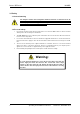
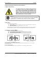
DOMEL Invento IFT Drives Document Version Number 6.0. DOMEL Invento IFT Drives Operating instruction These operating instructions can be used for all IFT drives. This operation instruction contains important technical advice and information about safety. Therefore please pay attention to this operation instruction before unpacking, installation or any other work is undertaken on this EC-controller! Indicates a general warning. Indicates a high-voltage warning.
Invento IFT Drives DOMEL 1.0 Safety 1.1 General warning The voltage of the EC drive is dangerous whenever the drive is connected to the AC line. Incorrect installation of the motor or drive may cause damage to the equipment, serious injury or death. Comply with the safety instructions in this manual as well as local and national rules and safety regulations. 1.2 Personal safety 1. Disconnect the EC drive from the AC line if repair work is to be carried out.
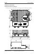
DOMEL Invento IFT Drives 2.0 Mechanical dimensions 2.1 Mechanical dimensions IP55 type The drawing below gives the mechanical dimensions of IFT EC drive - IP55 version. All dimensions are in millimetres. Version 6.
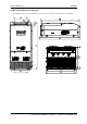
Invento IFT Drives DOMEL 2.2 Mechanical dimensions IP20 type The drawing below gives the mechanical dimensions of IFT EC drive – IP20 version. All dimensions are in millimetres. 5 Operating and Installation instructions Version 6.
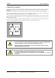
DOMEL Invento IFT Drives 3.0 Mechanical installation The EC drive is cooled by air circulation. IFT EC drive can be installed inside the AHU or on the motor console. It can be also installed on the wall. All types of IFT EC drive can be installed side-by-side. Domel recommended a minimum 50 mm space between them. The IFT EC mounts in virtually any position if sufficient cooling is assured. This free mounting position offers wide flexibility.
Invento IFT Drives DOMEL 4.0 General information about electrical installation 4.1 High voltage warning The voltage of the EC drive is dangerous whenever the drive is connected to the AC line. Incorrect installation of the motor or drive may cause damage to the equipment, serious injury or death. Comply with the safety instructions in this manual as well as local and national rules and safety regulations.
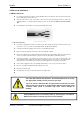
DOMEL Invento IFT Drives 5.0 Electrical installation 5.1 Mains and motor Use a shield / armoured motor cable to comply with EMC emission specifications, and connect this cable to both the decoupling plate and the motor metal. Keep the motor cable as short as possible to reduce the noise level and leakage currents. To reduce the operating problems, use shield cable. Max lengths of cables are described in Chapter 8: General technical data.
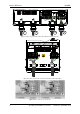
Invento IFT Drives DOMEL 2 3 YG 1 1 3 2 4 Figure 5a: Proper connection wire to the motor and mains terminals (IP55 type) 1 2 3 YG Figure 5b: Proper connection wire to the motor and mains terminals (IP20 type) Figure 6: How to Connect / Disconnect wire 9 Operating and Installation instructions Version 6.
DOMEL Invento IFT Drives 5.2 Connecting the electrical system Check whether the data on the type plate agrees with the connection data. Before connecting the device, ensure that the supply voltage matches the operating voltage of the device. Only use cables that are configured for the current according to the specification on the type plate. 5.2.
Invento IFT Drives 11 DOMEL 1 Potentiometer for set value / speed setting; R ≥ 1 kΩ 2 External sensor : 0 – 10 V output 3 Analogue voltage 0-10V / PWM / Pulse Speed output : Digital or analogue output; NPN open collector output (no external pull-up resistor needed ) 4 Fire mode: ON - switch open; OFF – switch closed, bridge to +24V terminal 5 ON/OFF: ON – switch closed – bridge to +24V terminal ; OFF – switch open Operating and Installation instructions Version 6.
DOMEL Invento IFT Drives 6.0 Functions 6.1 Fault Relay output The relay output can be used for giving the present status or warning. The relay is a Form C with contacts 1 and 2 normally closed. The output is activated when a given condition is fulfilled. Relay error function is activated if alarm situation is occurred in the IFT EC Drive: • Under voltage protection, • Overcurrent detection.
Invento IFT Drives DOMEL AN1_Min is set to 1V and parameter AN1_Max is set to 9V. In the picture above, controller works from RPM_Min = 200RPM to RPM_Max = 1500RPM. AN1 operates from 1V to 9V. Setting AN1_Stop parameter to 0V (Picture 1) means that AN1_Stop function is disabled and motor will run with minimal RPM also in case of voltage at AN1 input is 0V. In picture 2 AN1_Stop parameter is set to 1V.
DOMEL Invento IFT Drives Set RPM via AN1 or Potentiometer - ignore Set RPM via AN2 - ignore In Fire mode function electronics runs with parameters valid only for Fire mode functions (RPM, over temperature limits …). These parameters should be sets via MODBUS registers. The function should be enabled by disconnecting the terminal pins (10) and (11). We recommended installing a switch. To disable the function disconnect terminal pins (switch=ON).
Invento IFT Drives DOMEL Galvanic isolation (PELV) PELV (Protective Extra-Low Voltage) separation is achieved with galvanic separators betwee control circuits and circuits connected to the AC line potential. These separators meet the requirements for increased isolation in standard EN 50 178. Installation must be in accordance with local and national PELV regulations. All control terminals, terminals for serial communication and relay terminals are safely separated from the AC line potential, i.e.
DOMEL Invento IFT Drives 0x05: Write Single Coil 0x06: Write Single Holding Register To connect PC and DOMEL IFT Drive over serial line (MODBUS) RS-232/USB to RS-485 Converter is needed. We recommend ADAM-4561 converter. To attach the ADAM-4561 to a PC, you do not need to power down your PC. The power for the ADAM4561 converter is derived from the USB port, so there are no power adapters to deal with. The ADAM-4561 device driver can be used in combination with Windows 2000/XP/Vista/7 (32 & 64-bit).
Invento IFT Drives DOMEL 7.1.
DOMEL Invento IFT Drives Controller Configuration 34 100 Speed output mode 0: disabled (input) 1: 2..10V (1mA) 2: FREQ(10V, 1mA) 3: PWM(25mA) 4: PWM(10V,1mA) 5: 0..20mA 6: 0..10V (1mA) 7: 4..20mA 8: 2..10V (1mA) 0…9 6 1 W/1 / -10000…2 1 0.01% W/1 / Voltage for maximum setpoint Voltage for minimum setpoint 0 … 1000 0 … 1000 900 100 0.01 0.01 W/1 W/1 V V 0: disable stop function AN1_Stop > 0: Stop threshold voltage 0 … 1000 70 0.01 W/1 V *1 *1 0 0 0 0 0 NaN NaN 1 1 0.1 1 0.
Invento IFT Drives DOMEL 8.0 General technical data: Mechanical Data EC type IFT02 IFT03 IFT04 IFT06 IFT08 IFT11 Fig.1 (IP55 type), Fig. 2 (IP20 type) Physical appearance Dimensions, IP20 mm Dimensions, IP55 mm Weight, IP20 kg Weight, IP55 kg 335 x 155 x 118,5 / 332 x 281 x 112 / 5,5 4,0 6,2 5,5 6,5 7,2 7,5 Electrical Data Input Supply voltage Supply frequency 3 x 380 - 460 +10% / -10% V AC 50 / 60 Power consumption at max.
DOMEL Invento IFT Drives 9.