
Modbus Parameter Specifications


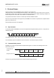
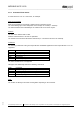


Table Of Contents
- Change history
- 1 Protocol frame
- 2 Holding registers
- 2.1 Overview
- 2.2 Reset
- 2.3 Set value
- 2.4 Password
- 2.5 Factory setting Control
- 2.6 Customer setting Control
- 2.7 Operating hours counter
- 2.8 Operating minutes counter
- 2.9 Addressing on/off
- 2.10 Stored set value
- 2.11 Enable RS485
- 2.12 Fan address
- 2.13 Set value source
- 2.14 Preferred running direction
- 2.15 Store set value
- 2.16 Mode of operation
- 2.17 Direction of action
- 2.18 Control parameters
- 2.19 Maximum modulation level
- 2.20 Minimum modulation level
- 2.21 Motor stop enable
- 2.22 Starting modulation level
- 2.23 Maximum permissible modulation level
- 2.24 Minimum permissible modulation level
- 2.25 Maximum speed
- 2.26 Maximum permissible speed
- 2.27 Ramp-up/ramp-down curve
- 2.28 Speed limit
- 2.29 Input characteristic curve
- 2.30 Maximum power
- 2.31 Maximum permissible power
- 2.32 Speed monitoring speed limit
- 2.33 Sensor actual value source
- 2.34 Interface settings
- 2.35 Rotating direction fail-safe mode
- 2.36 Fail-safe set value source
- 2.37 Set value for fail safe function
- 2.38 Time lag fail-safe speed
- 2.39 Cable break detection voltage
- 2.40 Sensor
- 2.41 Enable source
- 2.42 Stored enable RS485
- 2.43 Customer data
- 2.44 Error history
- 2.45 DC-link voltage reference value
- 2.46 DC-link current reference value
- 2.47 Manufacturing data
- 2.48 Air flow reference value
- 2.49 Mass flow reference value
- 2.50 Mirror function for holding registers
- 2.51 Mirror function for input registers
- 2.52 Mass flow calculation
- 3 Input registers
- 3.1 Overview
- 3.2 Identification
- 3.3 Maximum number of bytes
- 3.4 Bus controller software name
- 3.5 Bus controller software version
- 3.6 Commutation controller software name
- 3.7 Commutation controller software version
- 3.8 Actual speed
- 3.9 Motor status
- 3.10 Warning
- 3.11 DC-link voltage
- 3.12 DC-link current
- 3.13 Motor temperature
- 3.14 Temperature inside electronics
- 3.15 Current modulation level
- 3.16 Current set value
- 3.17 Sensor actual values
- 3.18 Enable input state
- 3.19 Current controller function
- 3.20 Current power
- 3.21 Current set value source
- 3.22 Energy consumption counter
- 3.23 Heartbeat
- 3.24 Mirrored input registers

MODBUS ACE V1.00
_______________________________________________________________________________________
ebm-papst Mulfingen GmbH & Co. KG
Bachmühle 2 ·74673 Mulfingen ·Phone: +49 (0) 7938/81-0 ·Fax: +49 (0) 7938/81-110 ·www.ebmpapst.com ·info1@de.ebmpapst.com
DocNo.: 634505DocNo: 446144DocNo.:358982DocNo.:322523DocNo.:309753DocNo.:303997DocNo.:276241DocNo.:256078DocNo.:196392 ·Template: 2 dated 10/6/2003 ·File: ext001931381.docx ·Last printed 9/30/2019 10:29:00
AM ·Page 7 of 78
Form 1003
1 Protocol frame
Data transmission using the MODBUS protocol defined in this specification
takes place solely in an environment defined as Master - Slave system. The ordered flow of data is governed
by the master. A slave has to respond to a command request from the master. When structuring a system, it is
therefore important to ensure that a slave address is not allocated twice.
The preferred transmission medium is a twisted-pair cable with RS485 standard.
RTU is the only transmission mode supported (see MODBUS over Serial Line Specification & Implementation
guide V1.0, Section 2.5.1)
ASCII transmission mode is not supported!
1.1 Byte structure
In accordance with the MODBUS over Serial Line Specification & Implementation guide V1.0, a byte has the
following structure:
Start
(low)
Bit 0
(LSB)
Bit 1
Bit 2
Bit 3
Bit 4
Bit 5
Bit 6
Bit 7
(MSB)
Parity
Stop
(high)
The parity bit ("Even", "Odd", "None") can be set with the "Parity configuration" parameter.
The transmission speed is variable and can be set with the "Transmission speed" parameter.
1.2 Communication process
MODBUS over Serial Line Specification & Implementation guide V1.0 defines the following frame for the
transmission protocol:
Command from
master:
Response from fan:
Address
8 bits
Command
8 bits
Data
N * 8 bits
CRC H
8 bits
CRC L
8 bits
Start
> 3.5 char
Address
8 bits
Command
8 bits
Data
N * 8 bits
CRC H
8 bits
CRC L
8 bits
Start
> 3.5 char
Contrary to the general specification the maximum telegram length is 80 bytes.