
Modbus Parameter Specifications


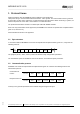
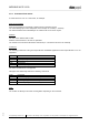


Table Of Contents
- Change history
- 1 Protocol frame
- 2 Holding registers
- 2.1 Overview
- 2.2 Reset
- 2.3 Set value
- 2.4 Password
- 2.5 Factory setting Control
- 2.6 Customer setting Control
- 2.7 Operating hours counter
- 2.8 Operating minutes counter
- 2.9 Addressing on/off
- 2.10 Stored set value
- 2.11 Enable RS485
- 2.12 Fan address
- 2.13 Set value source
- 2.14 Preferred running direction
- 2.15 Store set value
- 2.16 Mode of operation
- 2.17 Direction of action
- 2.18 Control parameters
- 2.19 Maximum modulation level
- 2.20 Minimum modulation level
- 2.21 Motor stop enable
- 2.22 Starting modulation level
- 2.23 Maximum permissible modulation level
- 2.24 Minimum permissible modulation level
- 2.25 Maximum speed
- 2.26 Maximum permissible speed
- 2.27 Ramp-up/ramp-down curve
- 2.28 Speed limit
- 2.29 Input characteristic curve
- 2.30 Maximum power
- 2.31 Maximum permissible power
- 2.32 Speed monitoring speed limit
- 2.33 Sensor actual value source
- 2.34 Interface settings
- 2.35 Rotating direction fail-safe mode
- 2.36 Fail-safe set value source
- 2.37 Set value for fail safe function
- 2.38 Time lag fail-safe speed
- 2.39 Cable break detection voltage
- 2.40 Sensor
- 2.41 Enable source
- 2.42 Stored enable RS485
- 2.43 Customer data
- 2.44 Error history
- 2.45 DC-link voltage reference value
- 2.46 DC-link current reference value
- 2.47 Manufacturing data
- 2.48 Air flow reference value
- 2.49 Mass flow reference value
- 2.50 Mirror function for holding registers
- 2.51 Mirror function for input registers
- 2.52 Mass flow calculation
- 3 Input registers
- 3.1 Overview
- 3.2 Identification
- 3.3 Maximum number of bytes
- 3.4 Bus controller software name
- 3.5 Bus controller software version
- 3.6 Commutation controller software name
- 3.7 Commutation controller software version
- 3.8 Actual speed
- 3.9 Motor status
- 3.10 Warning
- 3.11 DC-link voltage
- 3.12 DC-link current
- 3.13 Motor temperature
- 3.14 Temperature inside electronics
- 3.15 Current modulation level
- 3.16 Current set value
- 3.17 Sensor actual values
- 3.18 Enable input state
- 3.19 Current controller function
- 3.20 Current power
- 3.21 Current set value source
- 3.22 Energy consumption counter
- 3.23 Heartbeat
- 3.24 Mirrored input registers

MODBUS ACE V1.00
_______________________________________________________________________________________
ebm-papst Mulfingen GmbH & Co. KG
Bachmühle 2 ·74673 Mulfingen ·Phone: +49 (0) 7938/81-0 ·Fax: +49 (0) 7938/81-110 ·www.ebmpapst.com ·info1@de.ebmpapst.com
DocNo.: 634505DocNo: 446144DocNo.:358982DocNo.:322523DocNo.:309753DocNo.:303997DocNo.:276241DocNo.:256078DocNo.:196392 ·Template: 2 dated 10/6/2003 ·File: ext001931381.docx ·Last printed 9/30/2019 10:29:00
AM ·Page 8 of 78
Form 1003
1.2.1 Command from master
A master device is a PC or a control unit, for example.
Start synchronization:
Start synchronization is provided by a silent interval of at least 3.5 bytes.
The next following byte is then interpreted as the first byte of a frame (i.e. address).
The interval between the individual bytes of a frame must not exceed 1.5 bytes.
Address:
The size of the address field is 8 bits.
Address values between 1 and 247 are permitted
The address 0 is intended for broadcast commands (i.e. command to all fans in the network).
Command:
The following commands of the general specification "MODBUS Application Protocol Specification V1.1" are
supported:
Code
Command
0x03
Read holding register
0x04
Read input register
0x06
Write single register
0x08
Diagnostics
0x10
Write multiple register
The other commands are not supported.
ebm-papst has additionally defined the following commands:
Code
Command
0x43
Read holding register addressed by serial no.
0x44
Read input register addressed by serial no.
0x46
Write single register addressed by serial no.
0x50
Write multiple register addressed by serial no.
Data:
The number of data bytes and their meaning differ depending on the command.