
MAN 251–10BSE NO DK 20180903
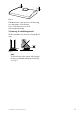
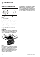
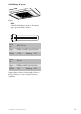
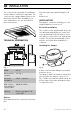
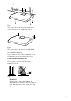
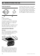

Table Of Contents
- Spiskåpa 251–10/B
- SV Bruksanvisning
- Emhætte 251–10/B
- DA Brugsvejledning
- Cooker hood 251–10/B
- GB User instructions
- Kjøkkenhette 251–10/B
- NO Bruksanvisning
- Fig. 9

INSTALLATION
The cooker hood is intended for installation
under, between or built into cupboards. The
cooker hood is equipped with a fluorescent
tube and polyester filter. Installation, use,
care, maintenance etc., are described in
these instructions.
TECHNICAL INFORMATION
Fig. 1
Width 60 cm
Other measu-
rements
see Fig. 1
Electrical
installation
230 V ~ earthed
Max. connec-
tion output for
control cable
900 W at 230 V ~
Lighting Fluorescent tube 11 W,
socket 2G7
Options
Drum attachment for connection to kitchen
flue.
Over-fan cupboard (cupboard height 110
cm).
Bracket set.
INSTALLATION
Fixing parts, screws for mounting, etc. are
supplied with the cooker hood.
Electrical installation
The cooker hood is supplied with an electri-
cal cable and earthed plug for connection
to an earthed wall socket as well as a con-
trol cable for connection to an external unit
or units. The junction box and wall socket
must be accessible after installation is
complete.
Installing the damper.
Fig. 2
A duct connector with damper is provided
inside the hood.
The damper shaft A should be positioned in
the eye under the damper cover; see {1}
Fig. 2. Make sure that the tabs B end up un-
der the edge of the plate and that the devi-
ce snaps into place.
16
991.0553.817/126364/2018-08-20