INSTRUCTIONS 67393E 04/19 (HJE) © 2019 OJ Electronics A/S OJ-DV OJ Drives® A DRIVES PROGRAMME DEDICATED TO VENTILATION SOLUTIONS
INSTRUCTIONS OJ-DV Contents 1. 2. 3. 4. 5. 6. 7. 8. 9. 10. 11. 12. 13. 14. 15. 16. 17. 18. 19. 20. 21. 22. 23. 24. Product presentation . . . . . . . . . . . . . . . . . . . . . . . . . . . . . . . . . . . . . . . . . . . . . . . . . . . . . . . . . . . . . . 4 Introduction . . . . . . . . . . . . . . . . . . . . . . . . . . . . . . . . . . . . . . . . . . . . . . . . . . . . . . . . . . . . . . . . . . . . . . 4 Key to symbols . . . . . . . . . . . . . . . . . . . . . . . . . . . . . . . . . . . . . .
INSTRUCTIONS OJ-DV | 25. 26. Fuse and Circuit Breaker Specifications . . . . . . . . . . . . . . . . . . . . . . . . . . . . . . . . . . . . . . . . . . . . . . . 30 Technical specifications . . . . . . . . . . . . . . . . . . . . . . . . . . . . . . . . . . . . . . . . . . . . . . . . . . . . . . . . . . . 31 Notice! The language used in the original documentation is English. Other language versions are a translation of the original documentation.
INSTRUCTIONS OJ-DV | General 1. Product presentation OJ-DV is a range of controllers suitable for regulating the speed of an electric motor in a wide variety of applications. OJ-DV is highly versatile as it can control various motor types, including: • ACIM - asynchronous induction motors • PMSM - permanent magnet synchronous motors 2. Introduction • Read this manual thoroughly and follow the instructions it contains before taking OJ-DV into use.
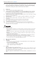
INSTRUCTIONS OJ-DV | General 4.11. OJ-DV contains capacitors which become charged during operation. These capacitors can remain charged even after the power supply has been cut off. There is a risk of severe personal injury if the connection terminals or wire ends are touched before these capacitors have been completely discharged. The discharge time is about 3 minutes under normal conditions. 5. Product use 5.1. OJ-DV is especially used in ventilation applications (fans). 5.2.
INSTRUCTIONS OJ-DV | General Table 7.2 Certification -4 EC Declaration of Conformity -5 -6 -7 - √ √ √ √ - - √ - √ √ - UL Recognised EAC 7.3. Product standard • In accordance with EN 61800-2 – Adjustable speed electrical power drive systems. Part 2. General requirements. 7.4. Safety • In accordance with EN 61800-5-1 – Adjustable speed electrical power drive systems. Part 5. Safety requirements – Electrical, thermal and energy. 7.5.
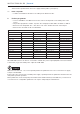
INSTRUCTIONS OJ-DV | General at the interface point between the user’s supply and the public system (Rsce). 7.7. RoHS compatible • Contains no hazardous substances according to the RoHS Directive. 8. Product programme • OJ-DV is available in four different enclosures, whose size depends on the rated power of the OJ-DV. • The product programme contains 13 power sizes ranging from 0.55 kW to 15.0 kW, see table 8. • Enclosures are designated ”H1”…”H5”, where ”H1” is the smallest and ”H5” is the largest.
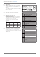
INSTRUCTIONS OJ-DV | General 9. Rating plate Figure 9.1 9.1. OJ-DV is equipped with a silver-coloured rating plate. See the example in fig. 9.1 and explanation in table 9.2. Check that the information specified on the rating plate is as expected. 9.2. Rating plate, information and explanation S S S S S Unit number IN: 3x380-480V, 50/60Hz,16.3/12.9A OUT: 3x0-0.9xVin, 0-120/400Hz, 19.0A IP65 / TYPE 4x Temp.-40 - +50ºC Wt. 3.9 Kg 5 703502 906812 Product ID = see table 10.4.
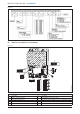
INSTRUCTIONS OJ-DV | Installation Figure 9.4 10. Exploded and dimensioned drawings BR1014A21b © 2016 OJ Electronics A/S Figure 10.1 7 8 1 6 2 5 4 BR1014A21b 3 Table 10.1 No. Description No.
8.5 10 125 22 40.5 40.5 67 50 52.25 184.5 50 52.25 20.7 220 55.2 © 2019 OJ Electronics A/S 144 47 29.5 66.5 21.5 244 68.5 66 8.5 BR1014A23a © 2015 OJ Electronics A/S 52.25 8.5 50 BR1014A23a 185 35 33 BR1014A22b © 2015 OJ Electronics A/S 8.5 10 52.25 BR1014A22b 34.5 40.5 50 8.5 Figure 10.4 100 10 40.5 10 265.5 BR1014A25a © 2015 OJ Electronics A/S Figure 10.2 10 399 67 8.5 52.25 BR1014A25a 185 BR1014A24a © 2015 OJ Electronics A/S 8.5 10 50 BR1014A24a 54.5 52.
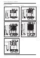
INSTRUCTIONS OJ-DV | Installation 11. Mechanical installation Warning Incorrect mechanical installation may cause overheating and impaired performance. • OJ-DV must only be installed by trained/experienced personnel. • To ensure proper cooling of the OJ-DV, it must be positioned in such a way that the passing air flow (> 3 m/s turbulent air speed) can cool the OJ-DV cooling fins. (3 m/s turbulent air speed is equivalent to 6.5 m/s laminar air speed).
INSTRUCTIONS OJ-DV | Installation Figure 11.3 12. BR1014A26a BR1014A05a BR1014A26a © 2015 OJ Electronics A/S BR1014A05a © 2015 OJ Electronics A/S Figure 11.2 Electrical installation Warning • OJ-DV must only be installed and commissioned by trained/qualified personnel. • Check that the data specified on the rating plate of the motor matches the data specified on the OJ-DV rating plate. • Incorrect electrical installation may cause a risk of severe or fatal personal injury. Advarsel 12.
INSTRUCTIONS OJ-DV | Installation Warning 12.4 Personal protection - use of RCDs (TT-system), direct current (AC/DC) risk This product can cause a DC current in the ground protective conductor in the event of a ground fault. If the 3 phases to the OJ-DV are not switched in at exactly the same time, then there will be a generated current in the earthing/ground conductor during the switching time until all 3 phases are connected.
INSTRUCTIONS OJ-DV | Installation • • • • • Use the clamps and connectors on the OJ-DV for proper ground connections. Do not “daisy chain” the ground connection between 2 or more OJ-DV controllers. Keep the ground conductor connections as short as possible. Always use shielded cables between the OJ-DV and motor, to reduce electrical noise. Follow motor manufacturer wiring requirements. Note 12.
INSTRUCTIONS OJ-DV | Installation Cable entries – cable glands – strain relief • The factory-fitted cable glands should be used when inserting power, motor and control cables into OJ-DV. • Remember to re-tighten the cable glands to ensure ingress protection and strain relief. • The Modbus cable entry features 3-point strain relief, which must be used. 12.10 Spring terminals • If multi-core cables/leads are used, core sleeves/ end sleeves must always be used.
INSTRUCTIONS OJ-DV | Installation Figure 12.12 U V W PE BR- BR+ Motor BR1014A09a © 2015 OJ Electronic A/S shielded cable and the shield must be ended in the clamp intended for that purpose. See fig. 12.12. • Remember to re-tighten the cable glands to ensure ingress protection and strain relief. 8-15mm © 2019 OJ Electronics A/S BR1014A27b © 2016 OJ Electronics A/S BR1014A16a 12.14 Modbus connection • OJ-DV is equipped with four connectors for Modbus connection.
INSTRUCTIONS OJ-DV | Installation • ”B”: Modbus connection, slave, no +24 V voltage in connector. • ”C”: Modbus connection, Master, external equipment, e.g. PTH/VOC. See fig. 12.11. • A 6-core, unshielded, 30 AWG/0.066 mm² telecommunications cable or similar type of ribbon cable can also be used for Modbus communication. • Attach RJ12 connectors to both ends using a special-purpose tool. • The OJ-DV is prepared to be installed in Modbus networks either in daisy chain or star networks.
INSTRUCTIONS OJ-DV | Installation • Din1 = Start/Stop (factory setting) • Digital input • Internal input impedance: 60 kΩ • Electrical connection, see fig. 12.15.4 Figure 12.15.3 Bus A Bus B Controller GND +10Vdc 0-10V In GND +Vout GND AoutX BR1014A18a Din2 Din1 Dout1 GND Figure 12.15.4 Bus A Bus B BR1014A19a © 2015 OJ Electronic A/S • Dout1 = Tacho Out; Open Collector (factory setting) • Digital output • Pull-up resistance range 1.
INSTRUCTIONS OJ-DV | Checklist 13. Checklist – mechanical and electrical installation • Before OJ-DV is energized for the first time,installation and connection must be checked. • Use the table below as a checklist. Item to be checked Description of check √ Completion Check that the entire installation is ready to be commissioned, both electrically and mechanically, before energizing the installation. Check that no people or animals are present in the vicinity of moving parts.
INSTRUCTIONS OJ-DV | Functions Figure 14.1 • The OJ-DV range can be connected to an HMI-35T hand terminal via Modbus RJ12 connector “A”. See fig. 14.1. • If an HMI-35T is connected, it will act as master and the OJ-DV as slave. • Only one master at a time can be connected to the RJ12 connectors marked ”A” and ”B”. It is thus not possible to connect both a hand terminal to connector ”A” and an active Modbus communication cable to connector ”B” at the same time.
INSTRUCTIONS OJ-DV | Functions 17. Functions 17.1 Analogue/digital control • OJ-DV can be controlled via analogue/digital (A/D) inputs or via Modbus. • The factory setting is analogue/digital (A/D) control. • Connect A/D control signals to the terminal strip, see section 12.15.1. 0-10V In • Is used to control motor speed in relation to a 0-10V signal.
INSTRUCTIONS OJ-DV | Functions a switching frequency of either 4 kHz or 8 kHz, or it can be set to change switching frequency automatically depending on motor speed (AUTO setting).
INSTRUCTIONS OJ-DV | Functions If you use the OJ-DV in frequency converter mode, you must connect a standard 3 phase~ AC-IM motor. Pay special attention to the information that you will find on the nameplate of the motor. The voltage output from the OJ-DV is for the OJ-DV-1005…..OJ-DV-1011 maximum 250 VAC. For the OJ-DV-3015…..OJ-DV-3150 the maximum voltage output is 364 VAC.
INSTRUCTIONS OJ-DV | Alarms 17.7 Electronically commutated mode (EC mode) – for PM The OJ-DV factory-set to frequency converter mode for standard asynchronous induction motors (AC-IM) and the control mode is 0-10 VDC input. This can be changed using the OJ-DV-PCTool or OJ-DV-HMI-35T (Hand terminal). The difference between an AC-IM motor and a PM-SM is basically the rotor.
INSTRUCTIONS OJ-DV | Alarms These three low and high rpm/Hz frequency bands must be configured via PC Tool, UDF or Modbus. Example: There is resonance in the application at 250 rpm. Program Low1 = 245 rpm & High1 = 255 rpm, and the OJ-DV will not let the motor run at a rpm between 245 and 255 rpm in other words; the OJ-DV jumps over the troublemaking 250 rpm. Tip: If there are problems with resonance at a specific rpm, there may also be problems at double the rpm.
INSTRUCTIONS OJ-DV | Maintenance and troubleshooting ✓ OJ-DV has reached the limit for maximum output power. ✓ The connected motor is larger than allowed for the chosen OJ-DV ✓ The load is too big for the connected motor. Warning ”RP” Earth fault (Only OJ-DV-3110 & OJ-DV-3150) ✓ Earth fault on motor cables or motor windings Alarm ”SA5” Running in the wrong direction ✓ Windmilling in the opposite direction during the start up process.
INSTRUCTIONS OJ-DV | Maintenance and troubleshooting = No connection between ”GND” and Add.Pin1/ Add.Pin2 = Connection between ”GND” and Add.Pin1/ Add.Pin2 • Via OJ-DV PCTool, where OJ-DV can be set to other Modbus addresses – see instructions for OJ-DV PCTool. Modbus protocol • Contact OJ Electronics A/S if you require a complete Modbus protocol. 22. Maintenance 22.1. OJ-DV is maintenance free under normal operating conditions and load profiles. 22.2.
INSTRUCTIONS OJ-DV | Maintenance and troubleshooting Symptom Cause Action Motor inoperative Lacking supply voltage Check the voltage supply to OJ-DV terminals ”L” and ”N” on 230V models (H1) or terminals ”L1”, ”L2” and ”L3” on 3x400V and 3x230V models (H3…H5). (Nominal supply voltage is stated on the rating plate.) Check whether short-circuit protection has been activated. Check that the voltage supply to OJ-DV has not been cut off by other components.
INSTRUCTIONS OJ-DV | Fuse and Circuit Breaker Specifications 23.4. Troubleshooting when OJ-DV is controlled via Modbus: Symptom Cause Action Motor inoperative Lacking supply voltage Check the voltage supply to OJ-DV terminals ”L” and ”N” on 230V models (H1) or terminals ”L1”, ”L2” and ”L3” on 3x400V and 3x230V models (H3…H5). (Nominal supply voltage is stated on the rating plate.) Check whether short-circuit protection has been activated.
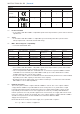
INSTRUCTIONS OJ-DV | 25. Fuse and Circuit Breaker Specifications 25.1 Overcurrent protection Provide overload protection to avoid overheating of the cables in the installation. Overcurrent protection must always be carried out according to local and national regulations. Suitable for use on a circuit capable of delivering not more than 5,000 rms symmetrical amperes, 480volt maximum.
INSTRUCTIONS OJ-DV | Technical specifications 26. Technical specifications Type Enclosure Power size Horsepower Efficiency Power supply Voltage Supply current at max. load at nominel supply voltage (400V/480V) Power factor (cos-phi) at max. load kW Hp % DV-1005 0.5 0.7 VAC A DV-1007 DV-1011 H1 0.75 1.1 1.0 1.5 > 94% DV-1013 H1x 1.3 1.7 DV-3015 1.5 2.0 DV-3024 H3 2.4 3.2 > 96.5% DV-3030 4.4 6.5 DV-3055 DV-3065 DV-3075 DV-3110 H4 3.0 4.0 4.0 5.4 DV-3150 H5 5.5 7.4 6.5 8.7 7.5 10.