S-BM2 Smoke Control Damper - MA multi Handbook
/110 | S-BM2 Table of Contents Overview . . . . . . . . . . . . . . . . . . . . . . . . . . . . . . . . . . . . . . . . . . . . . . . . . . . . . . . . . 3 Technical Parameters . . . . . . . . . . . . . . . . . . . . . . . . . . . . . . . . . . . . . . . . . . . . . . . . . .6 Diagrams . . . . . . . . . . . . . . . . . . . . . . . . . . . . . . . . . . . . . . . . . . . . . . . . . . . . . . . . . 9 Dimensions & Weights . . . . . . . . . . . . . . . . . . . . . . . . . . . . . . . . . . . . . . . . . .
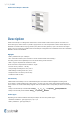
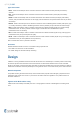
/110 | S-BM2 Smoke Control Damper - MA multi Description Smoke control dampers are designed for mechanical or natural smoke and heat extract systems. Its function is to extract toxic gases, smoke and fire or provide a supply of fresh air to fire compartments. Smoke control dampers are fitted with an actuator without a spring; therefore, they have two safety positions, “open” and “closed” and require power even in the event of fire.
/110 | S-BM2 Types of Activation • B230 - Smoke control damper with an activation mechanism with a Belimo actuator (230V AC) and auxiliary switches. • B24 - Smoke control damper with an activation mechanism with a Belimo actuator (24V AC/DC) and auxiliary switches. • B24-W - Smoke control damper with an activation mechanism with a Belimo actuator (24V AC/DC) and auxiliary switches, with provided cable connectors for the supply and communication unit (communication unit not part of the mechanism).
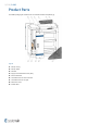
/110 | S-BM2 Product Parts The S-BM2 packaging for selected sizes also includes wooden manipulation jig.
/110 | S-BM2 Technical Parameters Durability Test 10000 cycles, actuator controlled (0 … 90 degrees rotation) – with no change of the required properties 10000 cycles, actuator controlled for "MOD" classification (45 ...
/110 | S-BM2 Allowed Pressure 1000 Pa Blade Tightness (EN 1751) Class 3 as standard Tightness of the Housing (EN 1751) Class C as standard Conformity with EC Directives 2006/42/ES Machinery Directive 2014/35/EU Low Voltage Directive 2014/30/EU Electromagnetic Compatibility Directive Driving Actuator Types Belimo BEN24, BEN230, BEN24-ST, BEN24-SR; BEE24, BEE230, BEE24-ST, BEE24-SR; BE24, BE230, BE24-ST; BLE24, BLE230, BLE24-ST Transport and Storage Dry indoor conditions with a temperature range of -20
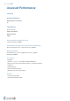
/110 | S-BM2 Assessed Performance 19 CE 1396 Systemair Production a.s.
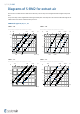
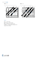
/110 | S-BM2 Diagrams of S-BM2 for extract air Accessories K1-S-BM2 and H1-S-BM2 do not affect the pressure drop and A-weighted total discharged sound power level. The pressure drop and A-weighted total discharged sound power level depend on the nominal width and height of the S-BM2 and air flow volume at different duct pressures. S-BM2 Grille Types 00, 01, 11, 22 S-BM2-...-00- S-BM2-...
/110 | S-BM2 S-BM2-...-11- S-BM2-...
/110 | S-BM2 S-BM2 Grille Types M0, M1 - 2 dampers vertically assembled into battery S-BM2-...-M0- S-BM2-...
/110 | S-BM2 S-BM2 Grille Types M0, M1 - 2 dampers horizontally assembled into battery S-BM2-...-M0- S-BM2-...
/110 | S-BM2 S-BM2 Grille Types M0, M1 - 4 dampers assembled into battery S-BM2-...-M0- S-BM2-...
/110 | S-BM2 Dimensions & Weights Dimensions of grille types 00, 01, 11, 02, 22 Note: *Inclusive grille Free area of grille types 00, 01, 11, 02, 22 325 H (mm) 425 625 825 1025 1225 GT 1000 950 900 850 800 750 700 650 600 550 500 450 400 350 300 250 200 150 125 A V (m2) W (mm) 0,021 0,025 0,033 0,042 0,050 0,058 0,067 0,075 0,084 0,092 0,100 0,109 0,117 0,125 0,134 0,142 0,150 0,159 0,167 0,014 0,017 0,023 0,029 0,035 0,040 0,046 0,052 0,058 0,063 0,069 0,075 0,081 0,086 0,092
/110 | S-BM2 Weights of grille types 00, 01, 11, 02, 22 1000 950 900 850 800 750 700 650 600 550 500 450 400 350 300 250 200 150 125 m (kg) W (mm) 20,1 20,7 21,8 23,0 24,1 25,3 26,5 27,6 28,8 29,9 31,1 32,3 33,4 34,6 35,7 36,9 38,1 39,2 40,4 325 20,5 21,1 22,3 23,5 24,7 25,9 27,1 28,3 29,5 30,7 31,9 33,2 34,4 35,6 36,8 38,0 39,2 40,4 41,6 20,9 21,5 22,7 24,0 25,3 26,5 27,8 29,0 30,3 31,5 32,8 34,1 35,3 36,6 37,8 39,1 40,4 41,6 42,9 24,9 25,6 26,9 28,3 29,6 31,0 32,3 33,7 35,0 36,4 3
/110 | S-BM2 Dimensions of grille type M0, M1 in battery type assembly
/110 | S-BM2 Note: *Inclusive grille Free area of grille type M0, M1 in battery type assembly 1530 H (mm) 1730 1930 2130 2330 2530 GT 1000 950 900 850 800 750 700 650 600 550 500 450 400 350 300 250 200 A V (m2) W (mm) 0,23 0,28 0,34 0,40 0,45 0,51 0,57 0,62 0,68 0,74 0,79 0,85 0,91 0,96 1,02 1,08 1,13 0,16 0,20 0,23 0,27 0,31 0,35 0,39 0,43 0,47 0,51 0,55 0,59 0,63 0,67 0,70 0,74 0,78 0,26 0,32 0,39 0,45 0,52 0,58 0,65 0,71 0,78 0,84 0,91 0,97 1,04 1,10 1,16 1,23 1,29 0,18 0,22
/110 | S-BM2 425 825 1025 1225 GT 2080 2030 1980 1930 1880 1830 1780 1730 1680 1630 1580 1530 1480 1430 1380 1330 1280 0,54 0,56 0,58 0,61 0,63 0,66 0,68 0,71 0,73 0,75 0,78 0,80 0,83 0,85 0,88 0,90 0,93 0,95 0,97 0,37 0,39 0,40 0,42 0,44 0,45 0,47 0,49 0,50 0,52 0,54 0,55 0,57 0,59 0,60 0,62 0,64 0,66 0,67 0,71 0,74 0,78 0,81 0,84 0,87 0,91 0,94 0,97 1,00 1,04 1,07 1,10 1,13 1,16 1,20 1,23 1,26 1,29 0,49 0,51 0,54 0,56 0,58 0,60 0,63 0,65 0,67 0,69 0,71 0,74 0,76 0,78 0,80 0,83 0,85
/110 | S-BM2 Weights of grille type M0, M1 in battery type assembly 1530 1930 2130 2330 2530 GT 1000 950 900 850 800 750 700 650 600 550 500 450 400 350 300 84,1 88,0 91,9 95,8 99,7 103,5 107,5 111,4 115,2 119,2 123,0 126,9 130,8 134,7 138,6 142,5 146,4 88,8 92,9 97,2 101,4 105,6 109,8 114,0 118,2 122,4 126,7 130,8 135,1 139,3 143,5 147,7 151,9 156,1 92,7 96,8 101,1 105,2 109,5 113,6 117,8 122,0 126,2 130,4 134,5 138,8 142,9 147,1 152,3 156,5 160,7 97,8 102,3 106,8 111,4 115,9 120,4 124
/110 | S-BM2 1530 H (mm) 1730 1930 2130 2330 2530 GT 2080 2030 1980 1930 1880 1830 1780 1730 1680 1630 1580 1530 1480 1430 1380 1330 1280 1230 1180 m (kg) W (mm) 203,4 207,0 210,5 214,2 217,8 221,3 224,9 228,5 232,1 235,7 239,3 242,9 246,5 250,1 253,6 257,2 260,8 264,4 268,0 216,0 219,8 223,7 227,6 231,5 235,4 239,2 243,1 247,0 250,9 254,8 258,7 262,6 266,5 270,3 274,2 278,1 282,0 285,9 222,7 226,6 230,5 234,4 238,3 242,1 246,0 249,9 253,8 257,7 261,6 265,5 269,4 273,2 277,1 281,
/110 | S-BM2 Ordering Codes W - Width Dimension 200 mm to 1000 mm and battery dimensions 1180 mm to 2080 mm. In step of 50 mm H - Height Dimensions 425 mm, 625 mm, 825 mm, 1025 mm, 1000 mm and battery dimensions 1530 mm, 1730 mm, 1930 mm, 2130 mm, 2330 mm, 2530 mm.
/110 | S-BM2 Installation Methods S-BM2 125 × 325 ... 1000 × 1225 1 Wet S-BM2 W > 1000, H > 1225 ... 2080 × 2530 S-BM2 125 × 325 ... 1000 × 1225 S-BM2 2 Dry 125 × 325 ... 1000 × 1225 S-BM2 125 × 325 ... 1000 × 1225 3 Soft S-BM2 W > 1000, H > 1225 ...
/110 | S-BM2 S-BM2 DBH DBV 125 × 325 ... 1000 × 1225 S-BM2 DMH DMV 125 × 325 ... 1000 × 1225 EI 120 (ved - i ↔ o) S1000Cmod HOT400/30 MAmulti EI 120 (hod - i ↔ o) S1000Cmod HOT400/30 MAmulti EI 120 (ved - i ↔ o) S1000Cmod HOT400/30 MAmulti EI 120 (hod - i ↔ o) S1000Cmod HOT400/30 MAmulti d) d) EN 1366-9 EN 1366-8 d) d) EN 1366-9 EN 1366-8 d) S-BM2 125 × 325 ... 1000 × 1225 EI 120 (hod - i ↔ o) S1000Cmod HOT400/30 MAmulti EN 1366-9 EN 1366-8 D1H, D2H d) S-BM2 D1V D2V 125 × 325 ...
/110 | S-BM2 • The distance between smoke control damper and the adjacent wall/ceiling and the smoke control damper must be at least 75 mm. • When the S-BM2 smoke control damper is installed into a smoke and fire partition structure, it must be placed so that the damper blades in its closed position are located inside this structure.
/110 | S-BM2 Installation 1. WET - in the Wall Using Plaster/Mortar/Concrete Filling 1.The supporting construction opening must be prepared as shown on picture. Opening surfaces must be even and cleaned off. The flexible wall opening must be reinforced as per the standards for plasterboard walls. The opening dimensions are driven by the nominal dimensions of the damper with added clearance. The opening will be with the dimensions of W1 and H1. 2.
/110 | S-BM2
/110 | S-BM2
/110 | S-BM2
/110 | S-BM2 Opening and wall/ceiling preparations
/110 | S-BM2 Damper minimum distances
/110 | S-BM2 Legend for installation 1. WET - in the Wall 1 - Smoke control damper S-BM2 2 - Connected ductwork made of Promatect-L500 boards (min. 500 kg/m3, Promat) 3 - Concrete/masonry/cellular concrete wall or ceiling 4 - Flexible (plasterboard) wall 4a - 2 layers of plasterboard fireproof plate type F, EN 520 4b - Vertical CW – profiles 4c - Horizontal UW – profiles 4d - Mineral wool; thickness/cubic density see picture.
/110 | S-BM2 Battery Installation, Grille type M0, M1
/110 | S-BM2
/110 | S-BM2 Fixing layout for battery installations
/110 | S-BM2 Opening and wall/ceiling preparations Damper minimum distances
/110 | S-BM2 Legend for installation 1. WET - in the Wall assembled in battery 1 - Smoke control damper S-BM2 2 - Connected ductwork made of Promatect-L500 boards (min.
/110 | S-BM2 Installation 1. WET - in the Ceiling Using Plaster/Mortar/Concrete Filling 1.The supporting construction opening must be prepared as shown on picture. Opening surfaces must be even and cleaned off. The opening dimensions are driven by the nominal dimensions of the damper with added clearance. The opening will be with the dimensions of W1 and H1. 2.Mount the hanger plates (A2) on the damper body only on the side which will be flush with the upper ceiling surface. 3.
/110 | S-BM2
/110 | S-BM2
/110 | S-BM2
/110 | S-BM2 Opening and wall/ceiling preparations Damper minimum distances
/110 | S-BM2 Legend for installation 1. WET - in the Ceiling 1 - Smoke control damper S-BM2 2 - Connected ductwork made of Promatect-L500 boards (min. 500 kg/m3, Promat) 3 - Concrete/masonry/cellular concrete wall or ceiling 4 - Flexible (plasterboard) wall 4a - 2 layers of plasterboard fireproof plate type F, EN 520 4b - Vertical CW – profiles 4c - Horizontal UW – profiles 4d - Mineral wool; thickness/cubic density see picture.
/110 | S-BM2 Installation 2. DRY Using Mineral Wool and Cover Boards 1.The supporting construction opening must be prepared as shown on picture. Opening surfaces must be even and cleaned off. The flexible wall opening must be reinforced as per the standards for plasterboard walls. The opening dimensions are driven by the nominal dimensions of the damper with added clearance. The opening will be with the dimensions of W1 and H1. 2.
/110 | S-BM2
/110 | S-BM2
/110 | S-BM2
/110 | S-BM2 Opening and wall/ceiling preparations
/110 | S-BM2 Damper minimum distances
/110 | S-BM2 Legend for Installation 2. DRY 1 - Smoke control damper S-BM2 2 - Connected ductwork made of Promatect-L500 boards (min. 500 kg/m3, Promat) 3 - Concrete/masonry/cellular concrete wall or ceiling 4 - Flexible (plasterboard) wall 4a - 2 layers of plasterboard fireproof plate type F, EN 520 4b - Vertical CW – profiles 4c - Horizontal UW – profiles 4d - Mineral wool; thickness/cubic density see picture. 5 - Grille 6 - Gypsum boards F2 - Mineral wool filling (min.
/110 | S-BM2 Installation 3. SOFT - in the Wall Using Mineral Wool filing 1.The supporting construction opening must be prepared as shown on picture. Opening surfaces must be even and cleaned off. The flexible wall opening must be reinforced as per the standards for plasterboard walls. The opening dimensions are driven by the nominal dimensions of the damper with added clearance. The opening will be with the dimensions of W1 and H1. 2.
/110 | S-BM2
/110 | S-BM2
/110 | S-BM2 Opening and wall/ceiling preparations Damper minimum distances
/110 | S-BM2 Legend for installation 3. SOFT - in the Wall 1 - Smoke control damper S-BM2 2 - Connected ductwork made of Promatect-L500 boards (min. 500 kg/m3, Promat) 3 - Concrete/masonry/cellular concrete wall or ceiling 4 - Flexible (plasterboard) wall 4a - 2 layers of plasterboard fireproof plate type F, EN 520 4b - Vertical CW – profiles 4c - Horizontal UW – profiles 4d - Mineral wool; thickness/cubic density see picture.
/110 | S-BM2 Battery Installation, Grille type M0, M1
/110 | S-BM2
/110 | S-BM2 Fixing layout for battery installations
/110 | S-BM2 Opening and wall/ceiling preparations Damper minimum distances
/110 | S-BM2 Legend for installation 3. SOFT - in the Wall assembled in battery 1 - Smoke control damper S-BM2 2 - Connected ductwork made of Promatect-L500 boards (min. 500 kg/m3, Promat) 3 - Concrete/masonry/cellular concrete wall or ceiling 4 - Flexible (plasterboard) wall 4a - 2 layers of plasterboard fireproof plate type F, EN 520 4b - Vertical CW – profiles 4c - Horizontal UW – profiles 4d - Mineral wool; thickness/cubic density see picture.
/110 | S-BM2 Installation 3. SOFT - in the Ceiling Using Mineral Wool filing 1.The supporting construction opening must be prepared as shown on picture. Opening surfaces must be even and cleaned off. The opening dimensions are driven by the nominal dimensions of the damper with added clearance. The opening will be with the dimensions of W1 and H1. 2.Mount the hanger plates (A2) on the damper body only on the side which will be flush with the upper ceiling surface. 3.
/110 | S-BM2
/110 | S-BM2
/110 | S-BM2
/110 | S-BM2 Opening and wall/ceiling preparations Damper minimum distances
/110 | S-BM2 Legend for installation 3. SOFT - in the Ceiling 1 - Smoke control damper S-BM2 2 - Connected ductwork made of Promatect-L500 boards (min. 500 kg/m3, Promat) 3 - Concrete/masonry/cellular concrete wall or ceiling 4 - Flexible (plasterboard) wall 4a - 2 layers of plasterboard fireproof plate type F, EN 520 4b - Vertical CW – profiles 4c - Horizontal UW – profiles 4d - Mineral wool; thickness/cubic density see picture.
/110 | S-BM2 Installation 3F. Fit Wall build around the damper, filled with mineral wool With this installation the wall is closed off by gypsum board layers around the damper after the insertion of the damper. 1.The opening dimensions are driven by the nominal dimensions of the damper with added clearance. The opening will be with the dimensions of W1 and H1. 2.Mount the bottom horizontal metal profile (4c) 20 mm below the destined bottom damper edge. 3.
/110 | S-BM2
/110 | S-BM2
/110 | S-BM2 Opening and wall/ceiling preparations
/110 | S-BM2 Damper minimum distances Legend for installation 3F. Fit 1 - Smoke control damper S-BM2 2 - Connected ductwork made of Promatect-L500 boards (min. 500 kg/m3, Promat) 3 - Concrete/masonry/cellular concrete wall or ceiling 4 - Flexible (plasterboard) wall 4a - 2 layers of plasterboard fireproof plate type F, EN 520 4b - Vertical CW – profiles 4c - Horizontal UW – profiles 4d - Mineral wool; thickness/cubic density see picture. 5 - Grille F2 - Mineral wool filling (min.
/110 | S-BM2 Installation DBH, DBV - in the Board Duct S-BM2 smoke control damper can be installed on “single” (tested according to EN 1366-9) or “multi” (tested according to EN 1366-8) ductwork. This section does not depict duct hanger rules as those are dependent on the weight of the duct itself and must be statically approved. Smoke control dampers must be suspended from solid ceiling slabs using adequately sized threaded rods.
/110 | S-BM2
/110 | S-BM2 Damper minimum distances Legend for installation DBH, DBV - in the Board Duct 1 - Smoke control damper S-BM2 2 - Connected ductwork made of Promatect-L500 boards (min. 500 kg/m3, Promat) 8 - Cover plate made of Promatect (min.
/110 | S-BM2 Installation DMH, DMV - in the Metal Duct S-BM2 smoke control damper can be installed on “single” (tested according to EN 1366-9) or “multi” (tested according to EN 1366-8) ductwork. This section does not depict duct hanger rules as those are dependent on the weight of the duct itself and must be statically approved. Smoke control dampers must be suspended from solid ceiling slabs using adequately sized threaded rods.
/110 | S-BM2
/110 | S-BM2 Damper minimum distances Legend for installation DMH, DMV - in the Metal Duct 1 - Smoke control damper S-BM2 5 - Grille 7 - Connected sheet metal ductwork tested according to EN 1366-8 or EN 1366-9 8 - Cover plate made of Promatect (min. 500 kg/m3, Promat) A2 - Hanger accessory H1-S-BM2 - can be made on site using 3 mm sheet metal plate. • For sizes W<550 or H<425 use 2 pieces on two damper edge. Total 4 pcs. • For sizes bigger than W=550 or H=425 use 3 pieces on each damper edge.
/110 | S-BM2 Installation D1H, D2H - Horizontally Oriented Damper, On the Duct S-BM2 smoke control damper can be installed on “single” (tested according to EN 1366-9) or “multi” (tested according to EN 1366-8) ductwork. If mounted on a duct classified with lover fire resistivity, the fire resistivity of S-BM2 smoke control damper will be decreased to the duct level. This section does not depict duct hanger rules as those are dependent on the weight of the duct itself and must be statically approved.
/110 | S-BM2
/110 | S-BM2
/110 | S-BM2 Damper minimum distances Legend for installation D1H, D2H - Horizontally Oriented Damper, On the Duct 1 - Smoke control damper S-BM2 2 - Connected ductwork made of Promatect-L500 boards (min. 500 kg/m3, Promat) 5 - Grille 8 - Cover plate made of Promatect (min. 500 kg/m3, Promat) A2 - Hanger accessory H1-S-BM2 - can be made on site using 3 mm sheet metal plate. • For sizes W<550 or H<425 use 2 pieces on two damper edge. Total 4 pcs.
/110 | S-BM2 Installation D1V, D2V - Vertically Oriented Damper, On the Duct S-BM2 smoke control damper can be installed on “single” (tested according to EN 1366-9) or “multi” (tested according to EN 1366-8) ductwork. If mounted on a duct classified with lover fire resistivity, the fire resistivity of S-BM2 smoke control damper will be decreased to the duct level. This section does not depict duct hanger rules as those are dependent on the weight of the duct itself and must be statically approved.
/110 | S-BM2
/110 | S-BM2
/110 | S-BM2
/110 | S-BM2 Damper minimum distances Legend for installation D1V, D2V - Vertically Oriented Damper, On the Duct 1 - Smoke control damper S-BM2 2 - Connected ductwork made of Promatect-L500 boards (min. 500 kg/m3, Promat) 5 - Grille 8 - Cover plates made of Promatect (min. 500 kg/m3, Promat) A2 - Hanger accessory H1-S-BM2 - can be made on site using 3 mm sheet metal plate. • For sizes W<550 or H<425 use 2 pieces on two damper edge. Total 4 pcs.
/110 | S-BM2 Electrical Connections IMPORTANT • Danger of electric shock! • Switch off the power supply before working on any electrical equipment. • Only qualified electricians are allowed to work on the electrical system.
/110 | S-BM2
/110 | S-BM2
/110 | S-BM2
/110 | S-BM2
/110 | S-BM2 Legend 1 - Remove the screws and remove the mechanism lid using the 2 straps. 2 - Drill holes in the predefined cut-outs or on the mechanism side of the damper body. 3 - Slide the power and communication wires through the drilled holes. 4 - Fix the wire to avoid any damage from pulling from the outside. 5, 10 - Connect the wires to the actuator or to the supply and communication unit. 6, 8, 11, 13 - Caulk all wire crossings properly using Promaseal A (Promat).
/110 | S-BM2 Electrical parameters per activation and actuator type AT B230 B24, B24-W B24-SR BST B...
B...
/110 | S-BM2 Type of activation B230 • Circuit switch between wires 2 and 3 is not part of the damper delivery. • When power supply is connected to wires 1 and 3, actuator drives to position OPEN. • When power supply is connected to wires 1 and 2, actuator drives to position CLOSED. Notes: • Caution! Main power supply voltage! • Parallel connection of several actuators possible.
/110 | S-BM2 Type of activation B24 • Circuit switch between wires 2 and 3 is not part of the damper delivery. • When power supply is connected to wires 1 and 3, actuator drives to position OPEN. • When power supply is connected to wires 1 and 2, actuator drives to position CLOSED. Notes: • Caution! Main power supply voltage! • Parallel connection of several actuators possible.
/110 | S-BM2 Type of activation B24-W This type of activation is with provided cable connectors for the supply and communication unit (communication unit not part of the mechanism). • Circuit switch between wires 2 and 3 is not part of the damper delivery. • When power supply is connected to wires 1 and 3, actuator drives to position OPEN. • When power supply is connected to wires 1 and 2, actuator drives to position CLOSED. Legend for activation type B24-W The actuator is fitted with connection plugs.
/110 | S-BM2 Type of activation B24-SR 24V AC/DC Belimo Actuator, modulated 0..10V • Circuit switch between wires 2 and 3 is not part of the damper delivery. • When power supply is connected to wires 1 and 3, actuator drives to position OPEN. • When power supply is connected to wires 1 and 2, actuator drives to position CLOSED.
/110 | S-BM2 Type of activation BST0 IMPORTANT: Danger of electric shock! Parallel circuits, i.e. a smoke detector on multiple slave devices are not allowed! Switch off the power supply before working on any electrical equipment. Allow only qualified electricians to work on the electrical system. Actuator power supply via fitted communication unit: DC 24 V. NOTES: • Connection scheme for fitted communication and supply unit BKNE230-24 (SBS/MP).
/110 | S-BM2 Legend for activation type BST0 1 - Power supply: cable and plug, AC 230 V. 2 - 3-pin connector: damper actuator (DC 24 V). 3 - 6-pin connector: damper actuator (position limit switches). 4 - 7-pin spring terminal: for 2-wire cable to the BKSE24-6 (2 x 1.5 mm² wire). • 1 up to 5not to be assigned. • 6 <-a-> terminal to BKSE24-6. • 7 <-b-> terminal to BKSE24-6. 5 - cable bushing for 2 wire cable to BKSE24-6. 6 - Green LED: damper closed. 7 - Yellow LED: damper open.
/110 | S-BM2 Type of activation BST1 IMPORTANT: Danger of electric shock! Parallel circuits, i.e. a smoke detector on multiple slave devices are not allowed! Switch off the power supply before working on any electrical equipment. Allow only qualified electricians to work on the electrical system. Actuator power supply via fitted communication unit: DC 24 V. NOTES: • Connection scheme for fitted communication and supply unit BC24-G2 (THC).
/110 | S-BM2 Legend for activation type BST1 X2 - 2-pin spring terminal: 1/2 - connection for SLC two-wire line, wires interchangeable. Maximum cable lengths can be calculated with the SLC Planning Tool. Rule of thumb: 300m@1.5 mm2. X3 - 3-pin connector: damper actuator (motor DC 24 V). X4 - 4-pin spring terminal: Connection for smoke detector. • 1- (+) DC 24 V / max. 30 mA. • 2- GND. • 3- IN1 (external relay contact 1). • 4- IN2 (external relay contact 2).
/110 | S-BM2 Type of activation BST10 IMPORTANT: Danger of electric shock! The BKNE230-24-PL may only be used with a designated master (e.g. BKS64PL). Switch off the power supply before working on any electrical equipment. Allow only qualified electricians to work on the electrical system.
/110 | S-BM2 Legend for activation type BST10 X6 and X300 connector terminals are arranged so that only either a conventional actuator or a Belimo Top-Line actuator can be connected.
/110 | S-BM2 S-BM2 Handling & Manipulation The S-BM2 is made of boards and can thus be considered fragile. Handling and manipulation must be done with care. Smaller dimensions can be manipulated and placed in the installation opening by two persons. Bigger dimensions are supplied with wooden blocks, those serve as support for suitable lifting equipment (forklift, crane). Please follow both textual and graphic instructions: 1.Unpack the damper and place it in vertical position. 2.
/110 | S-BM2
/110 | S-BM2
/110 | S-BM2 Legend Y1, Y2, Y3, Y4 - Cutting plane a) - For wall installation - insert the filling as per desired installation. b) - For duct installation – fix the hangers so that the weight of the damper is supported. Operation Manual After installation, it is necessary to adjust the damper into its operating position “closed”. In case, that the damper is used for extraction of pollutants, adjust the damper into its operating position “open”.
/110 | S-BM2 Functionality Check Switching the damper to the “open” position: • The blade must come to the fully open position within 60 seconds and must remain locked. • After reaching the end position of the blade, the appropriate signaling circuit must switch on – wires S1 and S2 must be connected. Switching damper to the “closed” position: • The blade must come up to the fully closed position within 60 seconds and must remain locked.
/110 | S-BM2 Supplement Any deviations from the technical specifications contained herein and the terms should be discussed with the manufacturer. We reserve the right to make any changes to the product without prior notice, provided that these changes do not affect the quality of the product and the required parameters.
Systemair DESIGN • 2022-07-11 • Handbook_S_BM2_en-GB • Original instructions