S-RA1 Smoke Control Damper - AAsingle Handbook
/31 | S-RA1 Table of Contents Overview . . . . . . . . . . . . . . . . . . . . . . . . . . . . . . . . . . . . . . . . . . . . . . . . . . . . . . . . . 3 Technical Parameters . . . . . . . . . . . . . . . . . . . . . . . . . . . . . . . . . . . . . . . . . . . . . . . . . .5 Diagrams . . . . . . . . . . . . . . . . . . . . . . . . . . . . . . . . . . . . . . . . . . . . . . . . . . . . . . . . . 7 Dimensions & Weights . . . . . . . . . . . . . . . . . . . . . . . . . . . . . . . . . . . . . . . . . . .
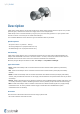
/31 | S-RA1 Description S-RA1 smoke control dampers operate with mechanical or natural smoke and heat extraction systems. They remove poisonous gases, smoke and fire and can also supply clean air to fire compartments. S-RA1 dampers have an actuator without a spring. Thus, they have two safety positions: an “open” position and a “closed” one. Power is necessary for the smoke control dampers. The “Installation Methods” section shows the types of installations that are permitted.
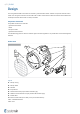
/31 | S-RA1 Design The casing and the blade of the S-RA1 are made of a galvanized sheet metal. A rubber seal prevents leaks of heat or smoke. The casing has connections on two sides with a rubber seal to attach to duct with nominal internal dimension. The dampers actuator of the S-RA1 is always accessible.
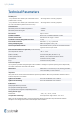
/31 | S-RA1 Technical Parameters Durability Test • Test procedure with 10000 cycles and actuator control (rotation from 0° to 90°) • No change of the necessary properties. • Test procedure with 10000 cycles and actuator control for “mod” classification (rotation from 45° to 60°) • No change of the necessary properties.
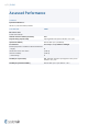
/31 | S-RA1 Assessed Performance 19 CE 1396 Systemair Production a.s. Hlavná 371, 900 43 Kalinkovo, Slovakia 1396-CPR-0207 S-RA1 EN 12101-8 : 2011 Smoke control damper Nominal activation conditions/sensitivity Pass Response delay (response time) Opening/closure time proven. Duration: <60 s / 90° Operational reliability Cmod: 20.
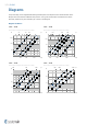
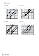
/31 | S-RA1 Diagrams The pressure drop, and A-weighted total discharged sound power level depend on the nominal diameter of the damper and air flow volume at different duct pressures. The type of activation does not influence the airflow parameter, therefore only one activation type is shown in the diagrams. Diagrams for Extract S-RA1-...-B230 S-RA1-...
/31 | S-RA1 S-RA1-...-B24-SR S-RA1-...-B24-SR Pressure drop & A-weighted sound power level in dB(A) Pressure drop & A-weighted sound power level in dB(A) 50 Pa 1000 100 150 l/s Size: 125, 75 % Size: 125, 50 % 800 300 Size: 200, 25 % 400 Size: 125, 0 % 55 dB(A) Size: 200, 0 % 55 dB(A) Size: 125, 100 % 45 dB(A) 50 dB(A) 35 dB(A) 40 dB(A) 25 dB(A) 250 200 500 45 dB(A) 50 dB(A) 35 dB(A) 25 dB(A) Size: 200, 100 % m³/h 500 1000 m³/h S-RA1-...-B24-SR S-RA1-...
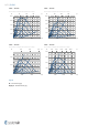
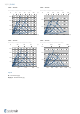
/31 | S-RA1 Diagrams for Supply S-RA1-...-B230 S-RA1-...-B230 Pressure drop & A-weighted sound power level in dB(A) Pressure drop & A-weighted sound power level in dB(A) Pa 200 50 100 200 55 Size: 100 35 50 40 40 30 35 30 35 25 25 25 200 Size: 250 40 40 35 30 25 25 10 25 55 45 30 25 30 20 35 30 30 m³/h 300 500 m³/h 500 1000 2000 S-RA1-...-B230 S-RA1-...
/31 | S-RA1 S-RA1-...-B24-SR S-RA1-...
/31 | S-RA1 Diagrams for Extract with Included GE1-S-RA1 Accessory S-RA1-...-B230 + GE1-S-RA1-...- S-RA1-...-B230 + GE1-S-RA1-...
/31 | S-RA1 S-RA1-...-B24-SR + GE1-S-RA1-...- S-RA1-...-B24-SR + GE1-S-RA1-...
/31 | S-RA1 Dimensions & Weights Dimensions (mm) S-RA1.../GE1-S-RA1... L1* ≤75 (220) 45 45 310 R1 10 10 DN-2,5 DN+15* L2* R2 Notes: Accessory GE1-S-RA1 sold separately. GE1-S-RA1 is not part of the S-RA1 delivery.
/31 | S-RA1 Free Area of S-RA1 Without Grille DN (mm) Av (m2) 100 S-RA1 125 140 150 160 180 200 225 250 280 315 355 400 450 500 560 630 0,005 0,008 0,01 0,012 0,014 0,019 0,024 0,032 0,04 0,051 0,067 0,086 0,111 0,143 0,178 0,226 0,289 Free Area of GE1-S-RA1 Accessory DN (mm) Av (m2) 100 125 140 150 160 180 200 225 250 280 315 355 400 450 500 560 630 GE1-S-RA1 0,003 0,005 0,007 0,008 0,010 0,013 0,016 0,022 0,027 0,035 0,046 0,060 0,077 0,097 0,121 0,154 0,198 Weig
/31 | S-RA1 Ordering Codes S-RA1 - - DN A DN Dimension, øDN: 100 mm, 125 mm, 140 mm, 150 mm, 160 mm, 180 mm, 200 mm, 225 mm, 250 mm, 280 mm, 315 mm, 355 mm, 400 mm, 450 mm, 500 mm, 560 mm, 630 mm A - Type of Activation B230 - 230V AC Belimo actuator B24 - 24V AC/DC Belimo actuator B24-W - 24V AC/DC Belimo actuator & wire connector for supply and communication unit B24-SR - 24V AC/DC Belimo actuator, modulated 0 V ...
/31 | S-RA1 Product Handling Warning Some damper parts can have sharp edges. To prevent injuries, use gloves when you install or move the damper. If you use or operate the damper incorrectly, there is a risk of: - electric shock. - fire. - other damage. Ensure that installation is performed by a trained person. The S-RA1 is made of sheet metal. Be careful when you move the smoke control damper. It is necessary to move the bigger dampers with suitable lifting equipment (forklift, crane).
/31 | S-RA1 1. 2. 1 4. 3. 2 × F1 2 i F1 1 2 F1 5. Legend for Product Handling 1 - Smoke control damper S-RA1 2 - Connected metal ductwork F1 - Screw M4×13 mm 6.
/31 | S-RA1 Installation Methods DMV E600 120 (ved i ↔ o) S1000 CMOD AAsingle d) S-RA1 DN 100 ... DN 630 D1V EN 1366-9 E600 120 (ved i ↔ o) S1000 CMOD AAsingle d) Notes: d) - Duct per EN 1366-9 ved - Duct placement, vertically oriented damper Installation Rules • The duct connected to the smoke control damper must be supported or hung in such a way that the damper does not carry its weight.
/31 | S-RA1 Installation DMV Vertically Oriented Damper, in the Metal Duct The S-RA1 smoke control damper can be installed on these types of ductwork: • “single” ductwork from sheet metal tested to EN 1366-9 or with higher density/thickness. • builders work ducts (created on site). This section does not give information about duct hanger rules. These rules are related to the weight of the duct and they must have static approval.
/31 | S-RA1 DMV 1 Y1 2 Y1 310 ≤150 1 Y1 2 F1 DN 1 2 (mm) A1 1 Y2 2 Y2 310 A1 ≤150 DN L2 F1 2× Legend for installation DMV: 1 - Smoke control damper S-RA1 2 - Connected metal ductwork A1 - Extension with grille (GE1-S-RA1), sold separately F1 - Screw M4×13 mm Y1, Y2 - Cutting planes 2 1 F1 (mm)
/31 | S-RA1 Installation D1V Vertically Oriented Damper, on the Duct The S-RA1 smoke control damper can be installed on these types of ductwork: • “single” ductwork from sheet metal tested to EN 1366-9 or with higher density/thickness. • builders work ducts (created on site). This section does not give information about duct hanger rules. These rules are related to the weight of the duct and they must have static approval.
/31 | S-RA1 (mm) D1V 00 ≥2 2 2 Y Y 1 1 0 0 ≥2 Y 310 A1 2 ≤150 L2 DN 1 F1 (mm) 00 ≥2 2 2 Y Y 1 1 A1 A1 0 0 ≥2 F1 F1 2× 2× Legend for installation D1V: 1 - Smoke control damper S-RA1 2 - Connected metal ductwork A1 - Extension with grille (GE1-S-RA1), sold separately F1 - Screw M4×13 mm Y - Cutting plane
/31 | S-RA1 Electrical Connections WARNING • Risk of electric shock. • Stop the power supply before you do work on electrical equipment. • Only approved electricians can do work on the electrical system. To access the electrical parts of this product follow instructions in "Product Handling" section.
/31 | S-RA1 Type of Activation B230 • The circuit switch between wires 2 and 3 is not part of the damper supply. • When the power supply is connected to wires 1 and 3, the actuator moves to the OPEN position. • When the power supply is connected to wires 1 and 2, the actuator moves to the CLOSED position.
/31 | S-RA1 Type of Activation B24 • The circuit switch between wires 2 and 3 is not part of the damper supply. • When the power supply is connected to wires 1 and 3, the actuator moves to the OPEN position. • When the power supply is connected to wires 1 and 2, the actuator moves to the CLOSED position.
/31 | S-RA1 Type of Activation B24-W This type of activation has cable connectors for the supply and communication unit (the communication unit is not part of the mechanism). • The circuit switch between wires 2 and 3 is not part of the damper supply. • When the power supply is connected to wires 1 and 3, the actuator moves to the OPEN position. • When the power supply is connected to wires 1 and 2, the actuator moves to the CLOSED position.
/31 | S-RA1 Type of Activation B24-SR 24V AC/DC Belimo Actuator, modulated (0)2..10V • When power supply is connected to wires 1 and 3, actuator drives to position OPEN. • When power supply is connected to wires 1 and 2, actuator drives to position CLOSED. Notes: • CAUTION: Main power supply voltage! • Parallel connection of more actuators possible when the power consumption and switching threshold is observed! • Operating range Y - DC (0)2...10 V • Input Impedance - 100 kΩ • Position feedback U - DC 2..
/31 | S-RA1 Type of Activation BST0 • The actuator and the control module are factory wired. • Connect the supply voltage to the connecting cable (approx. 1 m, with ferrules). • The 2-wire cable a/b to the BKSE24-6 is connected to terminals 6 and 7 (screw terminals for 2 x 1.5 mm^2 wire). Terminals 1 and 5 may not be assigned. • The BKNE230-24 transmits the damper position OPEN/CLOSED and fault messages to the BKSE24-6.
/31 | S-RA1 Operation Manual Functionality Check After you install the damper, make sure that you set it to its “closed” operating position. If you use the damper to remove pollutants, make sure that you set it to its “open” operating position. Connect the actuator to the related electric power supply (refer to the “Electrical connections” section). This procedure starts the actuator and sets the damper to its operating position.
/31 | S-RA1 To do a visual check of the internal parts of the damper, dismount the inspection lid or the grille. This will give you access to the internal parts. Also, if the damper has an mechanism lid, you can open the lid to access the internal parts. Do a check of these items of the internal side of the damper: • Make sure that there are no foreign objects or layers of contamination in the air distribution systems of the damper.
Systemair DESIGN • 2022-02-17 • Handbook_S_RA1_en-GB • Original instructions