Geniox Air handling unit User Manual Document in original language | EN Version 1.
Geniox Air Handling Unit - User Manual | 3060386
Detailed table of contents on the following pages General description A Manufacturer B Name of machines C General descriptions, dangers and warnings D Employees in charge of operation/control/maintenance E Intended use and range of applications F Unintended use and misuse – inappropriate applications for the machine Installation G Instructions for unloading on the site as well as installation and connection Start-up, adjustments and operation H Start-up, adjustments, use and commissioning I Information abou
A Manufacturer ................................................................................................................................................................................................ ..........1 A.1 Identification................................................................................................................................................................................................... 1 A.2 Unit inspection.....................................................
H.4.9 Space pressure sensors..............................................................................................................................................................31 H.4.10 Damper actuators........................................................................................................................................................................31 H.4.11 Room/Space temperature sensors................................................................................
Geniox Air Handling Unit - User Manual | 3060386
Manufacturer A | 1 Manufacturer This User Manual covers all air handling units with control system delivered by Systemair NA. Manufacturer and supplier data: Systemair NA 8 Rouse Street Tillsonburg, ON N4G 5W8 A.1 Identification Please keep this page for future reference. You have just purchased a Geniox Series Air Handling Unit. This design is certified by TUV SUD America (TUV) and bears the label indicating it has been tested to the current safety standards UL 1995 and CAN/CSA 22.2 NO.
2 A.4 | Manufacturer Geniox limited warranty Systemair warrants the Equipment manufactured by Systemair for a period of the lesser of 12 months from initial start-up or 18 months from date of shipment, whichever is less, against failure due to defects in material and manufacture and that it has the capacities and ratings set forth in Company’s catalogs and bulletins (“Warranty”).
Nomenclature B Nomenclature This manual covers Systemair Geniox Air Handling Units, sizes 10 thru 40. AHU Designation 12 345 6789 1011 12 Designation Tag Option Description 1 Series GNX Geniox Unit 10 Coil Size = 10 sq.ft, nominal 5,000 cfm 12 Coil Size = 12 sq.ft, nominal 6,000 cfm 15 Coil Size = 15 sq.ft, nominal 7,500 cfm 20 Coil Size = 20 sq.ft, nominal 10,000 cfm 25 Coil Size = 25 sq.ft, nominal 12,500 cfm 30 Coil Size = 30 sq.ft, nominal 15,000 cfm 35 Coil Size = 35 sq.
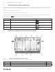
4 | C General description, danger and warnings General descriptions, dangers and warnings Geniox air handling units are order specific machines available in thousands of different configurations. Only a few examples of machine configurations are described below. The air handling units are intended for the transport and treatment of air between -40°F and +110°F. The units are exclusively for comfort ventilation. Maintenance of the units must be carried out by skilled technicians.
General desription danger and warnings Position Description 3 Damper - supply air 4 Filter - supply air 5 Fan- supply air 6 Heating coil - supply air 7 Fan - return air 8 Energy recovery wheel 9 Filter – return air 10 Damper – return air 11 Integrated control system in a cabinet behind this inspection door. Geniox nameplate Weight of the section. Production number of the unit. Number of the section in the unit.
6 | C.1.3 General description, danger and warnings Pictogram on a door for a fan in a Geniox unit Example of the pictogram with the symbol for the function - fan. Direction of arrow indicates the direction of the air flow. C.1.
General desricption danger and warnings | 7 Each of the above has the potential, if misused or handled improperly, to cause bodily injury or death. It is the obligation and responsibility of rigging, installation, and operating/service personnel to identify and recognize these inherent hazards, protect themselves and industry accepted safety practices when working on the units.
8 | General description, danger and warnings Caution labels: CAUTION HOT SURFACES INSIDE Don’t touch to avoid possible skin burns. Disconnect and lockout power and allow unit to cool before servicing. ATTENTION NE PAS TOUCHER pour éviter d'éventuelles brûlures de la peau. Débranchez et verrouillez l'alimentation et laissez l'unité refroidir avant de procéder à l'entretien.
General desription danger and warnings C.2.
10 | C.
Instruction for unloading on the site as well as installation and connection F.1 | 11 Air handling unit in operation The pressure difference between interior and exterior of the unit must not exceed 8 in w.g.. Before start-up of the unit, all ducts and protective devices must be mounted to prevent any access to rotating fan impellers. All inspection doors must be closed and locked when the unit is in operation. Do not use the unit without filters.
12 G.1.4 | Instruction for unloading on the site as well as installation and connection Pre-assembly storage The AHU must be protected from the weather and accidental impact. Plastic packaging must be removed and the unit covered with tarpaulin or similar materials. In order to minimize condensation, sufficient air circulation must be ensured between the covering and the unit. G.2 G.2.
Instruction for unloading on the site as well as installation and connection G2.3 | 13 Outdoor units — support under the base frame of the unit The installer must provide a platform that supports the base frame of the unit under the inspection side and under the back side of the unit. The frame must support the base frames of the unit under the entire length of the unit.
14 G.2.4 | Instruction for unloading on the site as well as installation and connection Installation on the site of unit sections Caution It is strictly forbidden to lift a section under the top of the section. The plastic corners and brackets are not at all reinforced for lifting the unit under the top. There is serious risk of injury and damage to property from heavy components falling. Pull sections together with a strap.
Instruction for unloading on the site as well as installation and connection | 15 Note: Never place the strap on the vertical profile too close to a corner, because the plastic corners and the profiles are not reinforced for the heavy load and stress created by the tensioner when a section is pulled along the base frame or on the floor. Place the strap on the bottom profiles of the unit to avoid any load and stress on the vertical profiles when sections are pulled together along the base frame.
16 | Instruction for unloading on the site as well as installation and connection G.2.5 Joining the AHU sections Position the unit sectional modules directly opposite each other Ensure that the internal factory-fitted rubber sealing is undamaged Section Clamps (Shipped loose) must then be installed using the table below for placement. Side Mount Rule** Number and positioning Service/Access Inside If height < 23-5/8” (600 mm) 1 in the middle If height ≥ 23-5/8” (600 mm) 2 pcs.
Instruction for unloading on the site as well as installation and connection Successful assembly is as shown: G.2.5.1 | 17 Each Geniox Section will have inner reinforcement brackets installed as shown: Outdoor Sectional Roof Sealing Outdoor sectional units require sealing where the roof panels meet and therefore the following steps must be taken to ensure a watertight seal: 1.
18 | G.2.5.2 • • • • Instruction for unloading on the site as well as installation and connection Joining the sectional baseframe Place sectional base frames lifting lug to lifting lug as shown in view below. Install lifting lug reinforcement plate between each lifting lug before securing section. Attach sections with nut and bolt as shown below. Torque all bolts to 44 ft-lb. G.2.
Instruction for unloading on the site as well as installation and connection G.2.8 | 19 Hood installation instructions Hoods are shipped loose for field install. 1. Apply caulking to hood mating surface, all the way around. 2. Align hood(s) to AHU opening. Ensure appropriate clearance for doors and other access points. 3. Affix the hood(s) to the AHU using sheet metal screws, beginning with uppermost hood. 4. Clean excess caulking squeezed from between mating surfaces. G.2.8.
20 | Instruction for unloading on the site as well as installation and connection 3. Seal the double-wall panel on each side with an industrial/ commercial grade silicone sealant or duct seal compound. It is extremely important to seal each panel hole or penetration securely so that it is airtight, watertight, and that there is no exposed foam insulation.
Instruction for unloading on the site as well as installation and connection G.3 | 21 Installation - electrical G.3.1 Description Electrical installations must comply with the current electrical standards of the region the unit is to be installed. Locate unit wiring diagrams inside. Refer to the unit wiring diagrams for position of components, wiring, connection point, and fuse size information.
22 | G.3.4 Instruction for unloading on the site as well as installation and connection Electrical connection of components and functions Cables are numbered for appropriate termination for internal and external connections. These numbers can also be found on the wiring diagram. G.4 G.4.1 Installation – Pipes for water – hot and chilled, valves and drains Description If ordered with the unit, the valves and valve motors are stored in a carton box placed inside the unit.
Instruction for unloading on the site as well as installation and connection G.4.4.3.2 | 23 Valve actuator and valve for heating The valve and valve actuator are not installed. 2-way or 3-way valve is available. G.4.4.3.3 Valve actuator and valve for cooling The valve and valve actuator are not installed. 2-way or 3-way valve is available G.4.
24 | Star-up, adjustments, use and commissioning Remember to check that there is water in the water trap. Table 1 Negative pressure P (in w.g.) H1 = H2 + H3 Where, H3 = 1 inch for each inch of negative pressure + 1 inch H2 = ½ *H3 Table 2 Positive pressure P (in w.g.) H1 = H2 + H3 Where, H3= ½ inch (minimum) H2 = ½ inch + unit positive static pressure at coil discharge with loaded/dirty filters. Notice: Installation of water trap is not included. H Start-up, adjustments, use and commissioning H.
Star-up, adjustments, use and commissioning | 25 H.
26 | Star-up, adjustments, use and commissioning Energy Recovery Wheel Assembly Wheel Spin Freely No. Wheel Motors Check Rotation HP Wheel Motor Amps: _______ L1 (Amps) L2 (Amps) L3 (Amps) 1 2 Exhaust Fan / Return Fan Assembly Alignment No.
Star-up, adjustments, use and commissioning | 27 Distech controller check off list (If applicable) Supply Fan Speed N/A Min Max Relief Fan Speed N/A Min Max Set point: ___________ Temperature Unit of Measure °C Humidity (Hot Gas Reheat) N/A °F ________% Scheduled Times Entered CO2 Unit Of Measure N/A PPM Motion Jumper Remote Inputs (N/A - Not Applicable, A - Analog, D - Digital) Temperature Sensor Mixed Air N/A A D Pass Outdoor Air N/A A D Pass Discharge Air N/A A D Pass
28 | Star-up, adjustments, use and commissioning Heat / Cool N/A A D MUX Pass N/A A D MUX Pass Heat Enable Heat 1 Heat 2 Cool 1 Cool 2 ERW Unoccupied Economizer Cool Heat Occupied Economizer Cool Heat Freeze Condition CO2 RH _____________ Notes: _________________________________________________________________________________________________ ______________________________________________________________________________________________________ _________________________________
Star-up, adjustments, use and commissioning 3060386 | Geniox Air Handling Unit - User Manual | 29
30 | H.4 Star-up, adjustments, use and commissioning Description of functions H.4.1 Remote control H.4.1.1 Communication to BMS systems via BACnet If Systemair has supplied the controls for the Geniox unit, network communication using BACNet communication protocol is available. Depending on the controls that have been provided, either BACNet/IP or BACNet MS/TP is available for communication with a BMS system (Building Management System).
Star-up, adjustments, use and commissioning H.4.9 | 31 Space pressure sensor When room/space pressure control is requested, a differential pressure sensor will be shipped for installation in the field. The pressure sensor will be required to be installed according to the manufacturer’s instruction. H.4.10 Damper actuators The units will be provided with a modulating damper motor with spring return function. They are powered by a 24 VAC signal and are controlled by a 2-10 VDC signal. H.4.
32 | Information about the residual risks I Information about the residual risks I.1 Unit casing I.1.1 Safe means of transport Hazards/dangerous area: • Incorrect handling during transport could result in the unit being dropped and damaged. Dangerous incident: • Dropped Units could result in serious injury or death Claim for reduction of danger: • Correct handling during transportation is described in this manual. If lifted by fork-lift truck the forks of the truck must be sufficiently long.
Information about the residual risks I.1.5 Filters I.1.5.1 Risk caused by missing change of filters | 33 Hazards/dangerous area: • Missing change of filters and missing maintenance decrease the capacity and final consequence will be breakdown. Dangerous incident: • By extensive lack of filter change and maintenance the machine can break down. Claim for reduction of danger: • In the manual is the method and schedule for change of filters and maintenance specified. I.1.5.
34 | Instruction on the protective mainteance during repair and maintenance I.1.7 Heating Coils I.1.7.1 Extreme temperatures - heating Hazards/dangerous area: • Electric Heater Manual Reset – 200°F Electric Heater Auto Reset – 125°F • Maximum Temperature for Hot Water Coil and Piping – 200°F Dangerous incident: • Here is no direct risk of burns. (short-time contact – lesser than 2,5 sec). Claim for reduction of danger: • No. I.1.7.
Adjustment and maintenance operations M | 35 Adjustment and maintenance operations Must be performed by skilled technicians. M.1 Shutdown of the unit to a safe state Warning Hazardous Voltage can cause electrical shock and burns. Disconnect power before proceeding with any work on this equipment, observe operating instructions and wear appropriate personal protective equipment (PPE). Turn off main disconnect switch and check that no voltage is present on the load side of the switch.
36 | Adjustment and maintenance operations M.3 Recommended maintenance intervals Function Maintenance Number per year Unit casing Cleaning of the unit casing 1 Control of rubber seals on doors and between sections. 1 Change on demand by alarm and always minimum twice a year. 2 Control of rubber seals. Control of the system with lateral locking rails and handles on Geniox10 – Geniox25. 2 Cleaning of all parts.
Adjustment and maintenance operations | 37 Panel filter location and size (HxW - Dimensions in inches) Geniox Size 1 2 3 Geniox 10 24 x 20 24 x 20 24 x 20 Geniox 12 24 x 20 24 x 20 Geniox 15 24 x 24 Geniox 20 24 x 20 Geniox 25 Geniox 30 4 5 6 7 8 24 x 20 24 x 12 24 x 12 24 x 12 24 x 24 24 x 24 24 x 12 24 x 12 24 x 12 24 x 20 24 x 20 20 x 12 20 x 12 24 x 24 24 x 24 24 x 24 24 x 20 24 x 24 24 x 24 24 x 24 24 x 24 Geniox 35 24 x 24 24 x 24 24 x 24 Geniox 40 24
38 | Adjustment and maintenance operations Bag filters are available in MERV 9 and 14 rating. Other MERV ratings can also be ordered. Bag filters are 15 inch deep. Panel filters are available in MERV 8 and 13 ratings. Other MERV ratings can also be ordered. 2 inch deep panel filters are available as a standard option. 4 inch deep panel can also be ordered. Note: Special sizes of filters and MERV ratings are available from Camfil. M.4.
Adjustment and maintenance operations Place the self-adhesive strip on one vertical side of the filter fame Check that the end of the strip is fully even with the horizontal side of the filter frame. Remove excess of the strip. The end of the strip must be fully even with the horizontal side of the filter frame. Push the filters carefully in the U-profile to be sure that there are no leakages between the filters.
40 | Adjustment and maintenance operations The end of the last filter is fully even with the end of the U-profile. The rubber profile on the inspection door will close the gap between inspection door and filter. Job is done. Check that rubber profiles on the back panel as well as rubber profiles on the inspection door are without wear and damage — still sufficient for avoiding any air leakage. M.4.2 Panel filters The filter cell guide rails are to be cleaned before fitting the new filters.
Adjustment and maintenance operations M.5 | 41 Other Components to maintain M.5.1 The unit It is very easy to remove inspection doors for access to cleaning, service, repairs and replacement of components in the unit. Lift the stainless steel shaft in the hinge to remove the door The unit should be cleaned once a year when operating with normal air quality for comfort ventilation with no special hygiene requirements.
42 | Adjustment and maintenance operations The damper blades are fitted with synthetic bearings requiring no lubrication. Air-tightness of the damper, when the damper motor is in the closed position, must be visually checked once a year. The damper motor is to be adjusted if the damper does not close tightly. M.5.3 Energy recovery wheel The energy wheel is to be checked at least once a year to ensure that it can turn freely and easily.
Instructions to enable adjustment and maintenance safely M.5.10 | 43 Plug fans Dust can accumulate on the fan impeller which can cause imbalance and vibrations. The fan impeller must therefore be checked once a year and cleaned, if necessary. Anti-vibration mounts and flexible connections should be checked at the same time. If the anti-vibration mounts are damaged in any way they must be replaced. M.5.
44 | N.1.2 Instructions to enable adjustment and maintenance safely Personal protective equipment for maintenance staff – health and safety Use the below-mentioned personal protective equipment for maintenance: • Cut-resistant gloves for protection against injury from sharp metal plate edges. • Hard Hat • Particulate respirator – maintenance free including foam face-seal and adjustable pre-threaded headbands – for replacing filters.
Annex Geniox Air handling unit User Manual Document in original language | EN Part number of this manual 3060386
Content Annex 1 Annex 2 Annex 3 Annex 4 Annex 5 Annex 6 Annex 7 Declaration of conformity with production number (in separate cover) ................................................................. ...............1-1 Technical data – unique data for every unit (in separate cover) .............................................................................................2-1 Spare part list ...............................................................................................
Spare Part List | 3-1 Annex 3 Spare part list Printed on separate pages but not delivered with every unit. Available on demand. Instructions for use: This spare parts list contains no safety regulations and is merely intended to assist in the ordering of spare parts. For information about operating, servicing, or repairing, the relevant safety and operating instructions must be consulted at all costs.
4-1 | ERW maintenance Annex 4 ERW maintenance Applies to Innergy tech Wheels installed in Geniox Units 4.1 ERW Bearing Wheel bearings are greased before shipping, but it is recommended to grease them again before start-up. Proper care and maintenance of the wheel bearings should allow it to last for up to twenty years. The recommended lubrication interval is every 6 months.
ERW maintenance | 4-2 Belt tensioner replacement The belt tensioner replacement is achieved by following these simple steps: 1) Lift the locking pin while pushing down on the motor to release the belt tension (a). 2) Incline the motor to remove the belt around the tensioner (b). 3) Unscrew the belt tensioner (c). 4) Install a new tensioner with a small angle inclined away from the motor (about 5-degree angle).
4-3 | ERW maintenance Belt Installation To install a spare belt or reduce the length of the current belt, follow these 5 easy steps: 1. Open/separate the belt by twisting the link tabs sideways and pulling the surplus out of the belt (see image below). If needed, adjust the length of the belt by replacing or removing the undesired links. a. Twist tab at a 90° angle b. Pull link out c. Twist belt end d. Pull out belt end 2. Tape one end of the belt on the perimeter of the wheel.
ERW maintenance | 4-4 3. Pull the belt tightly around the wheel and the gear reducer’s pulley. Connect both ends of the belt (see above image d. to a.). 4. Pass the belt over the tensioner idler sheave and place the motor to its initial position (a). 5. Visually inspect that the belt is not twisted around the rotors and is properly located through the side seals. If the belt tension is too low (see figure), reduce the length of the belt. 4.
4-5 | ERW maintenance Bill of Materials 4 9 Apply LOCK TITE #242 REC. TORQUE: 117 in-LB 6 2 5 8 1 3 ITEM PART # DESC QTY 1 2 09713 JAM NUT 1/4-20 Z.P.
ERW maintenance | 4-6 2. Refer to the “A” dimension (1) in the drawing below, identify and place marks (2) where the top 2 holes of the motor holder bracket and section base frame meet. 3. Place marks 5/8” (3) from the inside of the I4 corner tubing on both sides.
4-7 | ERW maintenance Caution Do not allow a visible space between the contact wheel and the I4 wheel. While the wheels rotate, a maximum of 1/32” of space is allowed. Note: Make sure the contact wheel rests entirely on the rotor perimeter. 2. Using clamping tools, adjust the EDD assembly into the correct position on the I4 corner tubing. Figure: Incorrect Contact Wheel Alignment 3. Once correctly positioned, fully install the 2 top self drilling screws on both inner sides of the I4 vertical tubing.
ERW maintenance | Caution At this stage, do not install tensioning spring rods fully to allow for further adjustments. Spring Assembly & Adjustment 1. Through the 2 factory-drilled holes (1), insert the 2 tension spring hooks onto the bottom frame of the motor holder bracket. 2. Install 2 jam nuts onto 2 tensioning spring rods (2). 3. Attach 2 tensioning spring rods to the 2 tension springs (3). 4. Insert 2 tensioning spring rods through the swivel motor holder (4). 5.
4-9 | ERW maintenance Caution Make sure the motor or cable does not stick out of the I4 wheel. Motor Junction Box Assembly 1. Using supplied hardware, install motor junction box parallel to the EDD assembly onto the I4 front tubing as shown (1). 1 4.5 Figure: Correct Junction Box Location ERW Seals The patented AirLoopTM labyrinth seals face the media along the center line of the rotor.
ERW maintenance | 4-10 If deformation to the lips can be seen, the seal is installed too close and should be moved back until the lips are straight again. The AirLoopTM labyrinth seal is made of a special material which was specifically chosen to ensure to never damage the media. While the best seal is obtained when the above steps are followed, if installed too close, the media will simply wear down the seal a little more.
4-11 | ERW maintenance LOW FRICTION SIDE & CENTER The low friction side and center seal are contact seals fixed to the wheel frame. The middle seals are located behind the pillow block bearings. The side seals are installed on the side of the rotor, along the depth dimension. They are factory installed and adjusted. No seal adjustment is required in the field. Caution While cleaning the wheel media, take care not to apply too much pressure to avoid damaging the wheel surface.
ERW maintenance 4.
4-13 | ERW maintenance 4.8 Service parts If part replacement is required, please contact service@systemair.net. For technical support, send pictures and summary explanation of the current situation. ERW Diameter Ref no. Seal 48 54 62 70 78 88 96 108 120 1 Driving belt 12’ 14’ 18’ 20’ 23’ 25’ 27’ 30’ 34’ Electric motor Ref no. 2 HP Voltage Phase Hz Part no.
Roof curb master tables 3060386 | Geniox Air Handling Unit - User Manual | 5-1
5-2 | Roof curb master tables Geniox Air Handling Unit - User Manual | 3060386
Roof curb master tables 3060386 | Geniox Air Handling Unit - User Manual | 5-3
5-4 | Roof curb master tables Geniox Air Handling Unit - User Manual | 3060386
Systemair NA 8 Rouse Street, Tillsonburg, ON, N4G 5W8 Toll free : 800.688.