
UserManual GenioxCore 250320
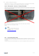


Table Of Contents
- A Manufacturer
- B Name of machines
- C Declaration of Conformity - example
- D General descriptions, dangers and warnings
- D.1 Overview via pictograms on the inspection side of the unit
- D.2 Data about the unit according to cards and labels in and on the unit
- D.2.1 Example of Machine card with unique data on every unit
- D.2.2 Label with data about the cabinet — example.
- D.2.3 Flowchart – example of the label placed on or with the cabinet
- D.2.4 Symbols in the flowchart and explanation about the symbols
- D.2.5 Example of label placed on or with the cabinet – Terminal plan for external components
- D.2.6 Control board for Systemair Access control system
- D.3 The control panel for the control system.
- D.4 Dimensions of the units
- D.5 Ordinary automatically operation – only manual operation by new parameters
- E Drawings, diagrams, guides and instructions for the use, maintenance and repair
- F Employees in charge of operation/control/maintenance
- G Intended use and range of applications
- H Unintended use and misuse – inappropriate applications for the machine
- I Instructions for unloading on the site as well as installation and connection
- I.1 Unloading on the site
- I.1.1 Handling methods
- I.1.2 Unloading by forklift truck
- I.1.3 Unloading by crane
- I.1.4 Transport of unit without base frame on the site
- I.1.5 Lifting a unit with straps
- I.1.6 Lifting a unit with installed brackets on the base frame for lifting.
- I.1.7 Lifting a unit without base frame and legs but with installed brackets for lifting.
- I.1.8 Handling a unit with holes in base frame for forks
- I.1.9 Roof unit with PVC, flat sheet steel plates or bitumen
- I.1.10 Roof unit with steel roof
- I.1.11 Pre-assembly storage
- I.1.12 Tilt less than 30˚ during transportation of the section with heat pump
- I.1.13 Transport and pre-installation storage of rotary heat exchanger — always in vertical position
- I.2 Installation - mechanical
- I.2.1 Free area in front of and above the unit
- I.2.2 Supporting surface
- I.2.3 Adjustable feet under legs or base frame and transport of sections
- I.2.4 Base frames for outdoor units
- I.2.5 Outdoor units — support under the base frame of the unit
- I.2.6 Installation on the site of unit sections.
- I.2.7 Video instruction — joining the sections
- I.2.8 Fitting the ductwork
- I.2.9 Risk of stack effect by vertical ducts and wind pressure on louvers
- I.2.10 Video instruction — installing dampers, coils and attenuaters in the ductwork
- I.2.11 Refitting of safety guards
- I.2.12 Lock the doors by using the key
- I.3 Installation - electrical
- I.4 Installation – Pipes for water – hot and chilled, valves and drains
- I.4.1 Description
- I.4.2 Pipe connections
- I.4.3 Possibility of extracting components from the unit
- I.4.4 Pipe connections to batteries
- I.4.5 Draining condensate water
- I.4.6 Video instruction — draining condensate water from heat exchanger
- I.4.7 Draining condensate water from cooling coil
- I.4.8 Roof of flat steel plates — connection of sections
- I.1 Unloading on the site
- J Installation and assembly instructions for reduction of noise and vibration emissions
- K Start-up, adjustments, use, commissioning and unit in hipernation
- K.1 Print-outs on paper
- K.2 Documentation is available for download
- K.3 Start-up by installer
- K.4 Video instructions about adjustments and use via the control panel
- K.5 Description of the control system functions
- K.5.1 Remote control
- K.5.2 Extended operation and external start/stop (for example by presence detectors)
- K.5.3 Valve and valve motor for heating coil
- K.5.4 Valve and valve motor for cooling coil
- K.5.5 DX cooling
- K.5.6 Circulation pump, heating
- K.5.7 Fire alarm function
- K.5.8 Electrical heater battery
- K.5.9 Speed control of fans
- K.5.10 Cabinet
- K.5.11 Temperature sensors
- K.5.12 Damper motors
- K.5.13 Filter guards
- K.5.14 Room temperature sensors
- K.5.15 Frost protection
- K.5.16 Systemair Control Panel - NaviPad
- K.5.17 Cooling recovery
- K.5.18 Free cooling
- K.5.19 Alarm signal
- K.5.20 Heat recovery
- K.5.21 Frost protection – plate heat exchanger
- K.6 Commissioning
- K.7 Accurate measuring of SFP (Specific Fan Power)
- K.8 Unit in hipernation — not in regular operation for several months
- L Information about the residual risks
- M Instructions on the protective measures during repair and maintenance
- N The essential characteristics of tools which may be fitted to the machinery
- O The conditions of stability during use, transportation, assembly, dismantling when out of service
- P Instructions for machinery where these are regularly to be transported
- Q The operating method to be followed in the event of breakdown. Safe restart.
- R Adjustment and maintenance operations
- R.1 Shutdown of the unit to a safe state
- R.2 Unlock and lock the doors by using the key
- R.3 Recommended maintenance intervals
- R.4 Filters – always replace filters with new filters with the same characteristics as original filters to maintain SFP value
- R.5 Changing the Internal Battery in the controller
- R.6 Functions to maintain
- S Instructions to enable adjustment and maintenance safely
- T The specifications of the spare parts to be used, when these affect the health and safety of operators
- U Information on airborne noise emissions exceeding 70 dB(A)
- Annex 1 Declaration of conformity with production number (in separate cover)
- Annex 2 Technical data – unique data for every unit (in separate cover)
- Annex 3 Spare part list (in separate cover — is only available on demand)
- Annex 4 Installation of steel roof of trapezoidal plates in the sizes 10 – 31
- 4.1 Overview
- 4.1.1 Mount rails. Units of size 10, 11, 12, and 14
- 4.1.2 Mount rails. Units of size 16 and units larger than size 16.
- 4.1.3 Roof overhang along the long sides of the unit
- 4.1.4 Calculation of the overhang at the ends of the unit. Mount overhang profile – G1.
- 4.1.5 Foam bands between rails and roof plates – mount roof plates.
- 4.1.6 Foam bands between roof plates
- 4.1.7 Mount roof plates – some of them are overlapping by 2 ribs
- 4.1.8 Mount overhang profile – G5 on the other end of the unit.
- 4.1.9 Mount side profiles and corners along the edges of the roof to protect persons
- 4.1.10 Apply sealing on plate joints to ensure water resistance.
- 4.1 Overview
- Annex 5 Speed control for rotary heat exchanger
- Annex 6 Reversible heat pump unit (in separate cover, if heat pump was delivered)
- Annex 7 Menu for internal controller in the heat pump unit (in separate cover, if heat pump was delivered)
- Annex 8 Connection of EC fan motor, diagnostics/faults and configuration of speed control
- Annex 9 Commissioning protocol – proposal (in separate cover)
- Annex 10 Report with data from final functional test on the Systemair factory (in separate cover)
- Annex 11 Short description of main components in the control system
- Annex 12 Wiring diagram (in separate cover)
- Annex 13 Operator’s guide (how to use the Systemair control panel) (in separate cover)
