
UserManual GenioxCore 250320
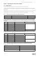
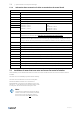
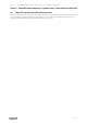
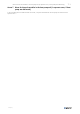
Table Of Contents
- A Manufacturer
- B Name of machines
- C Declaration of Conformity - example
- D General descriptions, dangers and warnings
- D.1 Overview via pictograms on the inspection side of the unit
- D.2 Data about the unit according to cards and labels in and on the unit
- D.2.1 Example of Machine card with unique data on every unit
- D.2.2 Label with data about the cabinet — example.
- D.2.3 Flowchart – example of the label placed on or with the cabinet
- D.2.4 Symbols in the flowchart and explanation about the symbols
- D.2.5 Example of label placed on or with the cabinet – Terminal plan for external components
- D.2.6 Control board for Systemair Access control system
- D.3 The control panel for the control system.
- D.4 Dimensions of the units
- D.5 Ordinary automatically operation – only manual operation by new parameters
- E Drawings, diagrams, guides and instructions for the use, maintenance and repair
- F Employees in charge of operation/control/maintenance
- G Intended use and range of applications
- H Unintended use and misuse – inappropriate applications for the machine
- I Instructions for unloading on the site as well as installation and connection
- I.1 Unloading on the site
- I.1.1 Handling methods
- I.1.2 Unloading by forklift truck
- I.1.3 Unloading by crane
- I.1.4 Transport of unit without base frame on the site
- I.1.5 Lifting a unit with straps
- I.1.6 Lifting a unit with installed brackets on the base frame for lifting.
- I.1.7 Lifting a unit without base frame and legs but with installed brackets for lifting.
- I.1.8 Handling a unit with holes in base frame for forks
- I.1.9 Roof unit with PVC, flat sheet steel plates or bitumen
- I.1.10 Roof unit with steel roof
- I.1.11 Pre-assembly storage
- I.1.12 Tilt less than 30˚ during transportation of the section with heat pump
- I.1.13 Transport and pre-installation storage of rotary heat exchanger — always in vertical position
- I.2 Installation - mechanical
- I.2.1 Free area in front of and above the unit
- I.2.2 Supporting surface
- I.2.3 Adjustable feet under legs or base frame and transport of sections
- I.2.4 Base frames for outdoor units
- I.2.5 Outdoor units — support under the base frame of the unit
- I.2.6 Installation on the site of unit sections.
- I.2.7 Video instruction — joining the sections
- I.2.8 Fitting the ductwork
- I.2.9 Risk of stack effect by vertical ducts and wind pressure on louvers
- I.2.10 Video instruction — installing dampers, coils and attenuaters in the ductwork
- I.2.11 Refitting of safety guards
- I.2.12 Lock the doors by using the key
- I.3 Installation - electrical
- I.4 Installation – Pipes for water – hot and chilled, valves and drains
- I.4.1 Description
- I.4.2 Pipe connections
- I.4.3 Possibility of extracting components from the unit
- I.4.4 Pipe connections to batteries
- I.4.5 Draining condensate water
- I.4.6 Video instruction — draining condensate water from heat exchanger
- I.4.7 Draining condensate water from cooling coil
- I.4.8 Roof of flat steel plates — connection of sections
- I.1 Unloading on the site
- J Installation and assembly instructions for reduction of noise and vibration emissions
- K Start-up, adjustments, use, commissioning and unit in hipernation
- K.1 Print-outs on paper
- K.2 Documentation is available for download
- K.3 Start-up by installer
- K.4 Video instructions about adjustments and use via the control panel
- K.5 Description of the control system functions
- K.5.1 Remote control
- K.5.2 Extended operation and external start/stop (for example by presence detectors)
- K.5.3 Valve and valve motor for heating coil
- K.5.4 Valve and valve motor for cooling coil
- K.5.5 DX cooling
- K.5.6 Circulation pump, heating
- K.5.7 Fire alarm function
- K.5.8 Electrical heater battery
- K.5.9 Speed control of fans
- K.5.10 Cabinet
- K.5.11 Temperature sensors
- K.5.12 Damper motors
- K.5.13 Filter guards
- K.5.14 Room temperature sensors
- K.5.15 Frost protection
- K.5.16 Systemair Control Panel - NaviPad
- K.5.17 Cooling recovery
- K.5.18 Free cooling
- K.5.19 Alarm signal
- K.5.20 Heat recovery
- K.5.21 Frost protection – plate heat exchanger
- K.6 Commissioning
- K.7 Accurate measuring of SFP (Specific Fan Power)
- K.8 Unit in hipernation — not in regular operation for several months
- L Information about the residual risks
- M Instructions on the protective measures during repair and maintenance
- N The essential characteristics of tools which may be fitted to the machinery
- O The conditions of stability during use, transportation, assembly, dismantling when out of service
- P Instructions for machinery where these are regularly to be transported
- Q The operating method to be followed in the event of breakdown. Safe restart.
- R Adjustment and maintenance operations
- R.1 Shutdown of the unit to a safe state
- R.2 Unlock and lock the doors by using the key
- R.3 Recommended maintenance intervals
- R.4 Filters – always replace filters with new filters with the same characteristics as original filters to maintain SFP value
- R.5 Changing the Internal Battery in the controller
- R.6 Functions to maintain
- S Instructions to enable adjustment and maintenance safely
- T The specifications of the spare parts to be used, when these affect the health and safety of operators
- U Information on airborne noise emissions exceeding 70 dB(A)
- Annex 1 Declaration of conformity with production number (in separate cover)
- Annex 2 Technical data – unique data for every unit (in separate cover)
- Annex 3 Spare part list (in separate cover — is only available on demand)
- Annex 4 Installation of steel roof of trapezoidal plates in the sizes 10 – 31
- 4.1 Overview
- 4.1.1 Mount rails. Units of size 10, 11, 12, and 14
- 4.1.2 Mount rails. Units of size 16 and units larger than size 16.
- 4.1.3 Roof overhang along the long sides of the unit
- 4.1.4 Calculation of the overhang at the ends of the unit. Mount overhang profile – G1.
- 4.1.5 Foam bands between rails and roof plates – mount roof plates.
- 4.1.6 Foam bands between roof plates
- 4.1.7 Mount roof plates – some of them are overlapping by 2 ribs
- 4.1.8 Mount overhang profile – G5 on the other end of the unit.
- 4.1.9 Mount side profiles and corners along the edges of the roof to protect persons
- 4.1.10 Apply sealing on plate joints to ensure water resistance.
- 4.1 Overview
- Annex 5 Speed control for rotary heat exchanger
- Annex 6 Reversible heat pump unit (in separate cover, if heat pump was delivered)
- Annex 7 Menu for internal controller in the heat pump unit (in separate cover, if heat pump was delivered)
- Annex 8 Connection of EC fan motor, diagnostics/faults and configuration of speed control
- Annex 9 Commissioning protocol – proposal (in separate cover)
- Annex 10 Report with data from final functional test on the Systemair factory (in separate cover)
- Annex 11 Short description of main components in the control system
- Annex 12 Wiring diagram (in separate cover)
- Annex 13 Operator’s guide (how to use the Systemair control panel) (in separate cover)

Installation of steel roof of trapezoidal plates in the sizes 10 – 31 |
4-7
4.1.9 Mount side profiles and corners along the edges of the roof to protect persons
Profiles N and O with the rectangular holes are for the long and lower side of the roof because rain can escape through
the holes. Mount the profiles type N first and the profile O last because the profile O goes over the profile N. Mounted
in this order, the profile O can match the end of the roof and the surplus length of the profile O will just cover part of
the previous profile N. Mount the profiles L and M along the long and higher front side of the roof. Mount the 4
protection corners.
4.1.10 Apply sealing on plate joints to ensure water resistance.
Finish installation of the steel roof by sealing all plate joints with silicone to prevent rainwater from passing into the
unit. See examples below of joints to be sealed.
output |