USB to Serial User Manual Version 3.05.1 2020/11/20 www.sysbas.
Revision History Revision Date Version Pages Description July/14/2006 2.0 All All new Aug/02/2008 2.1 Partial Partial edited May/13/2009 2.2 Partial Partial edited May/26/2009 2.3 Partial Partial edited Oct./26/2009 2.4 Partial Partial edited Feb./06/2010 2.5 Partial Partial edited Oct./18/2010 2.6 Partial Partial edited Nov./16/2010 2.7 Partial Partial edited July/19/2011 2.8 Partial Partial edited Apr./10/2012 2.9 All Partial edited Apr./27/2016 3.
USB to Serial User Manual Contents About Multiport(Multi-N) USB series ............................................................................................. 5 Multiport USB Specifications ......................................................................................................... 6 About latching USB ....................................................................................................................... 7 Connectivity Method ..............................................
USB to Serial User Manual About Multiport(Multi-N) USB series USB is a complex word of “Universal”, meaning all peripheral devices use the same connector, and “serial”, meaning devices are connected as a daisy chain through serial transmission. USB is an interface suggesting a solution to inconvenience and inefficiency caused by slow speed and limited device connection of existing external ports (serial or parallel).
USB to Serial User Manual Multiport USB Specifications - Hardware Number of Ports: 1, 2, 4, 8 USB Interface: USB Specification 1.1/2.0 Serial Interface: RS232 or COMBO(RS422/485) LED: Tx LED and Rx LED per each port Serial Connector: DB9 (Male) 1,2,4 DB9 (Male/Female) 4/8 Panel type Serial Communication Speed: 921.6Kbps maximum External Power: Optional *1 - Software (Driver) Supports Windows 7 or above. Linux Driver *2 Both 32 bit and 64 bit operating systems are supported.
USB to Serial User Manual About latching USB All USB Multiport products of SystemBase have latches on USB connection. Unlike traditional screw-tightening model which require specific cables and connectors, latching USB cable provides locking function without the need to replace the product. ※ USB latching function may be limited to some manufacturers. ※ For normal mounting, you might hear a ‘click’ sound. ※ To facilitate connection and disconnection, press lightly on the spring button and sweep it.
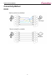
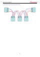
USB to Serial User Manual Connectivity Method RS232 8
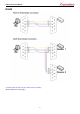
USB to Serial User Manual RS422 ※ Please check the pinout of your device before connecting (More example in the next page.
USB to Serial User Manual ※ Please check the pinout of your device before connecting 10
USB to Serial User Manual RS485 11
USB to Serial User Manual Termination Resistor What is a termination resistor? The purpose of using a termination resistor is to reduce the reflection wave in a network. Our USB to serial devices use 120 Ω resistor in RS422/RS485 communication when enabled.
USB to Serial User Manual RS485 Mode 13
USB to Serial User Manual Multi-1/USB Ver4.0 Multi-1/USB Ver4.0 is a model that supports USB1.1 and USB 2.0. It is detected automatically when it is connected to a USB port with a computer using Linux or Windows. It supports maximum communication speed of 921.6Kbps. Furthermore, it is equipped with surge protector to protect internal systems from outer shock. For Combo model, user can set and/or enable communication mode and terminal resistor.
USB to Serial User Manual 1. RS232 Model - DB9 Male Pin Assignment 2.
USB to Serial User Manual - Jumper Setting ① Loosen two screws on the bottom case. ② Remove the side caps. Look at the rear side of case, you can find the small grooved. ③ Top cover is slid to the inside of the case.
USB to Serial User Manual 10M: Disable slew rate limit feature. Maximum communication speed for this mode is at 921.6Kbps. 250K: Enable slew rate limit feature. Communication speed is limited to under 250Kbps. The slew rate limit feature allows communication without errors by activating slew-rate driver to reduce reflection waves and EMI electromagnetic waves. However, communication speed is limited when it is enabled.
USB to Serial User Manual Multi-2/USB Ver4.0 Multi-2/USB Ver4.0 is a model that supports USB2.0. It is detected automatically when it is connected to a USB port with a computer using Linux or Windows. It supports maximum communication speed of 921.6Kbps. Furthermore, it is equipped with surge protector to protect internal systems from outer shock. For Combo model, a user can set and/or enable communication mode and terminal resistor.
USB to Serial User Manual 1. RS232 Model - DB9 Male Pin Assignment 2.
USB to Serial User Manual - Jumper Setting ① Loosen four screws on the bottom case. ② Remove the side caps. Look at the rear side of case, you can find the small grooved. ③ Top cover is slid to the inside of the case.
USB to Serial User Manual 10M: Disable slew rate limit feature. Maximum communication speed for this mode is at 921.6Kbps. 250K: Enable slew rate limit feature. Communication speed is limited to under 250Kbps. The slew rate limit feature allows communication without errors by activating slew-rate driver to reduce reflection waves and EMI electromagnetic waves. However, communication speed is limited when it is enabled.
USB to Serial User Manual Multi-4/USB Ver4.0 Multi-4/USB Ver4.0 is a model that supports USB2.0. It is detected automatically when it is connected to a USB port with a computer using Linux or Windows. It supports maximum communication speed of 921.6Kbps. Furthermore, it is equipped with surge protector to protect internal systems from outer shock. For Combo model, a user can set and/or enable communication mode and terminal resistor.
USB to Serial User Manual 1. RS232 Model - DB9 Male Pin Assignment 2.
USB to Serial User Manual - Jumper Setting ① Loosen eight screws on the bottom case. ② Remove the side caps. Look at the rear side of case, you can find the small grooved. ③ Top cover is slid to the inside of the case.
USB to Serial User Manual 10M: Disable slew rate limit feature. Maximum communication speed for this mode is at 921.6Kbps. 250K: Enable slew rate limit feature. Communication speed is limited to under 250Kbps. The slew rate limit feature allows communication without errors by activating slew-rate driver to reduce reflection waves and EMI electromagnetic waves. However, communication speed is limited when it is enabled.
USB to Serial User Manual Multi-4U Ver1.7 Multi-4U Ver1.7 is a model that supports USB2.0. It is detected automatically when it is connected to a USB port with a computer using Linux or Windows. It supports maximum communication speed of 921.6Kbps. Furthermore, it is equipped with surge protector to protect internal systems from outer shock. If you use 5VDC adapter, the power can be supplied to 9th pin of DB9 with maximum 1A. For Combo model, a user can change communication mode with the switch.
USB to Serial User Manual 1. RS232 Model - DB9 Male Pin Assignment 2.
USB to Serial User Manual -Jumper Setting - RS232 RI: Use 9th pin of DB9 connector as RI signal (Default) Power: Use 9th pin of DB9 connector to supply +5V DC power. (Requires an adapter.
USB to Serial User Manual - COMBO NONE: Do not supply any power to 9th pin of DB9. (Default) +5V: Use 9th pin of DB9 to supply +5V DC power. (Requires an adapter.
USB to Serial User Manual 10M: Disable slew rate limit feature. Maximum communication speed for this mode is at 921.6Kbps. (Default) 250K: Enable slew rate limit feature. Communication speed is limited to under 250Kbps. The slew rate limit feature allows communication without errors by activating slew-rate driver to reduce reflection waves and EMI electromagnetic waves. However, communication speed is limited when it is enabled.
USB to Serial User Manual NONE: Disable termination resistors 422: Enable RS422 terminal resistor 485: Enable RS485 terminal resistor 32
USB to Serial User Manual Multi-8U Ver1.7 Multi-8U Ver1.7 is a model that supports USB2.0. It is detected automatically when user connects USB port with computer. It supports maximum communication speed of 921.6Kbps. Furthermore, it is equipped with surge protector to protect internal systems from outer shock. And, when a DC adapter is used, it can supply power thorough 9th pin of DB9 with maximum 1A. For Combo model, a user can set a communication mode with the switch.
USB to Serial User Manual 1. RS232 Model - DB9 Male Pin Assignment 2.
USB to Serial User Manual -Jumper Setting - RS232 RI: Use 9th pin of DB9 connector as RI signal (Default) Power: Use 9th pin of DB9 connector to supply +5V DC power. (Requires an adapter.) Mode: Used as power mode setting (Keep default. Do not temper with it.
USB to Serial User Manual - COMBO NONE: Do not supply any power to 9th pin of DB9. (Default) +5V: Use 9th pin of DB9 to supply +5V DC power. (Requires an adapter.) Mode: Used as power mode setting (Keep default. Do not temper with it.
USB to Serial User Manual 10M: Disable slew rate limit feature. Maximum communication speed for this mode is at 921.6Kbps. (Default) 250K: Enable slew rate limit feature. Communication speed is limited to under 250Kbps. The slew rate limit feature allows communication without errors by activating slew-rate driver to reduce reflection waves and EMI electromagnetic waves. However, communication speed is limited when it is enabled.
USB to Serial User Manual NONE: Disable termination resistors 422: Enable RS422 terminal resistor.
USB to Serial User Manual Multi-4U/8U V1.6 Multi-4U/8U V1.6 may operate with USB power only. But it can operate with an external adapter when it needs more stable power supply. It can supply +5V when the device requires. This feature is useful when small devices such as a cash box, a bar-code reader and a printer are connected to a PC POS system. +5V DC can be supplied even when Multi-4/8 USB is not using an external adapter. This power is supplied through 9th pin of DB9 connector.
USB to Serial User Manual - Specification Communication Speed Max 921.6Kbps Bus Interface USB 2.0 Cable Latching Connector applied, 1.5m(4.92ft) Signal RS232/RS422/RS485 Controller FTDI 2232D Connector DB9 Female Protection 15kV Surge Protector Supported OS Windows 7 or above Linux Kernel 2.6 or above Manufacturer SystemBase Co.
USB to Serial User Manual 1. RS232 Model - DB9 Female Pin Assignment - External Voltage Supply Jumper Multi-4U RS232 V1.6 Multi-8U RS232 V1.6 There are jumpers for each ports inside the case. Users can select modes by changing the position of a jumper. RI: Use 9th pin of DB9 connector as RI signal (Default) Power: Use 9th pin of DB9 connector to supply +5V DC.
USB to Serial User Manual 2. Combo (RS422/RS485) Model - DB9 Female Pin Assignment - Switch for selecting RS422/RS485 Signal Multi-4U Combo V1.6 Multi-8/USB Combo V1.
USB to Serial User Manual - Port# RT: RS422, RS485 Terminal Resistor Multi-4U Combo V1.6 Multi-8/USB Combo V1.6 422: Enable terminal resistor for RS422 485: Enable terminal resistor for RS485 NONE: Disable terminal resistors (Default) - External Voltage Supply - In Multi-4/8 USB Combo model, +5V is always supplied through the 9th pin of DB9 connector. Users can connect 9th pin to the device if they require to supply +5V DC to the device.
USB to Serial User Manual - Jumper for Slew Rate Setting The slew rate limit feature allows communication without errors by activating slew-rate driver to reduce reflection waves and EMI electromagnetic waves. However, communication speed is limited when it is used. Multi-4/USB Combo V1.6 Multi-8/USB Combo V1.
USB to Serial User Manual Manually Installing Windows Device Driver Install procedures for 64bit drivers are identical to 32bit drivers. 1. Run Windows 2. Connect USB Multiport to the USB port in the computer. 3. Download USB driver from SystemBase website(www.sysbas.com) and unzip the file. 4. Click “Hardware and Sound” from “Control Panel” 5. Following picture shows “Device Manager” after step 4. Click “Device Manager”.
USB to Serial User Manual 6. Right click “USB <-> Serial Cable” in “Device Manager”. Then Choose “Update Driver Software” 7. Click “Browse my computer for driver software” in order to install driver manually.
USB to Serial User Manual 8. Click “Browse” and set driver software’s location to: [Drive letter]: \Driver\32bit or [Drive letter]: \Driver\64bit 9. Confirm that “USB Serial Converter” is installed. Then, right click "USB Serial Port" and follow the same process from number 6 again.
USB to Serial User Manual 10. Following picture shows “Device Manager” after the drivers are installed. 11.
USB to Serial User Manual Automatic Driver Installation in Windows This procedure applies to Windows 7, 8, 8.1, 10. (32 and 64bits) The 32-bit setup utility does not work with 64-bit Windows, nor does the 64-bit setup utility work with 32-bit Windows. 1. Run Windows. 2. Connect USB MultiPort to the USB port in the computer. 3. Download USB driver from SystemBase website(www.sysbas.com) and unzip the file. Open the folder named [Drive letter]: \Driver\32bit or [Drive letter]: \Driver\64bit 4.
USB to Serial User Manual Windows Device Driver Setup 1. An advanced properties page is available for USB device. To access the advanced properties page, open "Device Manager” from “Control Panel”. Find the USB serial port you want to change the properties and right-click on it. Select "Properties" from the menu then select the "Port Settings" tab to get to the window below.
USB to Serial User Maual 2. This page allows configuration of the basic device parameters (i.e. Baud rate, data bits, parity, stop bits and flow control). To access more advanced settings, click on the "Advanced…" button to display the advanced properties page. (shown below) 3. This page will allow the following parameters to be altered: COM port number: You can change the serial port number.
USB to Serial User Manual - Devices that monitor these signals can enter the wrong state after an unplug-replug cycle on USB. Note that if \ the "Serial Enumerator" option in the property page is selected, then the enumeration sequence causes the modem control signals to change at startup. So if it is necessary to select "Disable Modem Ctrl At Startup", then it is likely that "Serial Enumerator" should be unchecked in the property page.
USB to Serial User Manual Manually Removing Windows Device Driver 1. Run “Device Manager”. Do not remove USB MultiPort from the USB port yet. USB Multiport should be removed after all removal processes are completed. 2. “USB Serial Converter A/B/C/D” controllers and “USB Serial Port” serial ports can be found. The number of ports may vary depending on the product you are using. Serial ports should be removed first.
USB to Serial User Manual 3. Find ‘USB Serial Port (COM#)’ under “Device Manager->Ports->USB Serial Port (COM#)” and right click on any “USB Serial Port”. Click “Uninstall”. 4. Check the following check box, and click “OK”. 5. Remove the rest of the USB serial ports.
USB to Serial User Manual 6. Unlike the previous Window when deleting, check box cannot be found. Click “OK” to remove current port. Repeat step 5~6 until all serial ports are removed. 7. “USB Serial Port” removal is now completed. We will now continue with “USB Serial Converter” removal. 8. Right click on one of the “USB Serial Converter” and click “Uninstall”.
USB to Serial User Manual 9. Check the “check box” and click “OK”. 10. Remove rest of “USB Serial Converters”.
USB to Serial User Manual 11. Repeat steps 10~11 until all USB serial converters are removed. 12. Remove USB MultiPort from USB connection port. 13. USB MultiPort drivers are now completely removed from your system.
USB to Serial User Manual Automatic Driver Uninstallation in Windows This procedure applies to Windows 32 and 64 bits. If you want to uninstall the device drivers manually, please refer to manual uninstallation pages. The 32-bit setup utility does not work with 64-bit Windows, nor does the 64-bit setup utility work with 32-bit Windows. 1. Run Windows. 2. Connect USB Multiport to the USB port in the computer. 3. Download USB driver from SystemBase website(www.sysbas.com) and unzip the file.
USB to Serial User Manual Serial port sorting program (USBSerial_Remap) The following is a description of the utility needed to change the serial port number or to sort sequentially when installing and using MultiPort /USB on a computer. Execution order of USB Serial_Remap 1. Restart your computer with the MultiPort / USB disconnected. 2. After restarting your computer, connect MultiPort / USB to USB connector. 3. Run USBSerial_Remap.
USB to Serial User Manual Multi-4U/8U Version History Version V 1.0 V 1.1 Feature Using V DC by 12V from an adapter 5V or 12V DC power supply by d-sub pin#9. Using linear regulator for V1.0 and switching regulator for V1.1. DC power has nothing to do with bus power supplied from USB port. DC power is used to supply power to d-sub pin#9. V 1.2 Use 5V DC adapter to supply 5V power Use 12V DC adapter to supply 12V power Provide power to d-sub pin#9 using external power supply, an adapter.
USB to Serial User Manual Copyright Copyright ⓒ 2020 SystemBase CO., Ltd. All rights reserved. This manual is a document protected by Copyright law. Unauthorized copying, duplicating, publishing of some or all of contents without prior consent from SystemBase is against Copyright Law. www.sysbas.
If you have any inconvenience while using the product, please contact us. Working Hour Email: • Purchase/Quotation: overseas@sysbas.com MON ~ FRI 9:00 ~ 18:00 • Technical Support/RMA: tech@sysbas.com www.sysbas.com Tel: Fax: +82-2-855-0501 +82-2-855-0580 Copyright ⓒ 2020 SystemBase Co., Ltd. All Right Reserved.