
User's Manual


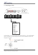


5. Install Input Cable
1
2
3
4
1
2
3
4
5
6
7
8
9
10
11
12
1
2
3
4
5
6
7
8
9
10
Power
Input Output
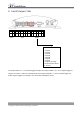
Input Connector
1 : Input1
2 : Input2/ACC
3 : Input3
4 : Input4
5 : Input5
6 : Input6
7 : Input7
8 : Input8
9 : Analog Input1
10 : Analog Input2
11 : Vout +5V
12 : Ground
The Input number 1, 2, 3, 4 are positive triggered inputs and Input number 5, 6, 7, 8 are negative triggered
inputs. If you would like to use power saving function, please connect the Input2/ACC to ACC wire. The
analog inputs are reserved.
Copyright © 2003 Systems & Technology Corporation