DJI MATRICE 600 User Manual V 1.0 2015.
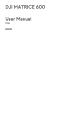
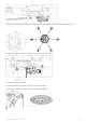
Installation Mounting the Frame Arms Propeller CW or CCW Mark Power Cables Propeller Cover Screw Holes ESC Signal Cable Screw Arm Tube Motor Arm Screws ESC Indicator 1. Preparing the frame arms. 1) Check all propellers for cracks. Ensure all the screws are secured in position. 2) Ensure all motors are mounted correctly and firmly and free from obstruction. 3) Ensure that all the cables are intact. 4) Mount all arms with red motor base to M1 and M2 (both sides of the N0.
5. Twist the red knob to lock each arm in place. Be sure there is an audible click, which indicates a proper lock. Check the arm for movement. To store, untwist the knob and lower the frame arm. 6. Remove the lower cover of the center frame to connect the power cables and the ESC signal cable. 7. Pull all the cables of the frame arm through the cable fixing ring on bottom of the center frame. 8. Plug each ESC signal cable into the slot near each arm on the center frame. 9.
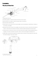
Mounting the Servo Set DO NOT mix the mounting position between the left and right servo set. Identify the left servo set by locating the control board that is integrated on the left servo set. Servo Control Board (Left servo set only) Servo Cable Power Cable 1. Insert the servo mounting rod into the outer mounting hole on the center frame, mounting holes on the servo set and inner mounting hole on the center frame respectively.
3. Align the cable fixing ring and the screw holes on the bottom of the servo set. Tighten the M3x5 screws. 4. Tighten the M3x6.5 screws to secure the servo set on the mounting rod. M3x6.5 5. Connecting the Servo Cables. 1) Connect the left servo cable to “L” port on the control board. 2) Connect the right servo cable to “R” port on the control board. Right Servo Cable ©2015 DJI. All Rights Reserved.
Mounting the Landing Gear Do not mix the cabling between the left and right servo, otherwise the landing gear cannot function properly. Arrange the wiring neatly to avoid the cables being cut by frame edges. The antennas are attached to the landing gears on its delivery. Pull out the antenna cables from the landing gear legs before mounting. Antenna Cable Antenna 1) Insert one landing gear leg into each landing skid tube and secure it in place by tightening the M3×8 (socket cap) screw.
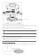
Lightbridge 2 Air System Wire Outlets 2. Open the fixing bracket and then remove the Lightbridge 2 air system. 3. Pull the two antenna cables from the triangular wire outlets (between M4 and M5) on the lower plate of the center frame. Connect them to the antenna ports on the Lightbridge 2 air system. 4. Mount the Lightbridge 2 air system back into the bracket. DO NOT damage the antenna cables. If using the AV / HDMI port of the Lightbridge 2 air system, connect the corresponding cables first. 5.
2. Connect the servo cables from No.1 to No.6 to the corresponding port of the flight controller. Connect the No.7 servo cable to the M7 port of the flight controller. Connect the No.9 servo cable to the iESC port of the flight controller. 3. Connect the Aircraft Status Indicator cable to the LED port of the flight controller. 4. Connect the DBUS port of the Lightbridge 2 air system to the RF port of the flight controller via the DBUS cable. Use the included DBUS cable ONLY.
Mounting the Upper and Lower Covers of the Center Frame 1. Re-mount the upper cover of the center frame. Note that the arrow points toward the nose (M1, M2) and DO NOT damage the cables. 2. Re-mount the lower cover of the center frame. Note that the two square holes are aligned to the two XT30 ports on the lower plate of the center frame. DO NOT damage the cables. 3. Connect the servo power cable to the XT30 port (6S LiPo) on the lower plate of the center frame. ©2015 DJI. All Rights Reserved.
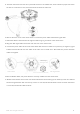
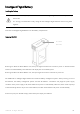
Intelligent Flight Battery Installing the Battery There are six battery compartments on the M600. Six intelligent flight batteries are required to fly the aircraft. It’s strongly recommended to fully charge all the intelligent flight batteries before using them together. Insert the six Intelligent Flight Batteries into the battery compartments. Powering ON/OFF Power Button (Built-in LED) Powering On: Press the Power Button once, then press again and hold for 2 seconds to power on.
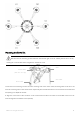
Remote Controller Preparing Remote Controller Tilt the Mobile Device Holder to the desired position then adjust the antenna as shown. Remote Controller Diagram [1] Antennas Relays aircraft control and video signal. [2] Mobile Device Holder Mounting place for your mobile device. [3] Control Stick Controls aircraft orientation. [4] Return Home (RTH) Button Press and hold the button to initiate Return to Home (RTH). [5] Transformation Switch Toggle the switch up or down to raise of lower the landing gear.
[7] Status LED Displays the power status. [8] Power Button Used to power on or power off the remote controller. [9] RTH LED Circular LED around the RTH button displays RTH status. [10] Camera Settings Dial Turn the dial to adjust camera settings. Only functions when the remote controller is connected to a mobile device running the DJI GO app. [11] Playback Button Playback the captured images or videos. [12] Shutter Button Press to take a photo.
[18] HDMI OUT Port Connect an HD compatible monitor. [19] USB Port Connect to mobile device to access all of the DJI GO app controls and features. [20] GPS Module Used to pinpoint the location of the remote controller. [21] Back Left Button Customizable button in DJI GO app. [22] Back Right Button Customizable button in DJI GO app. [23] Power Port Connect to a power source to charge the remote controller’s internal battery.
Charging Remote Controller Charge the remote controller via supplied charger. Controlling Camera Shoot videos or images and adjust camera settings via the Shutter Button, Camera Settings Dial, Playback Button and Video Recording Button on the remote controller. [1] Camera Settings Dial Turn the dial to quickly adjust camera settings such as ISO and shutter speed without letting go of the remote controller. Move the dial button to left or right to view the pictures or videos in playback mode.
Press once to start recording video, then press again to stop recording. Connecting Mobile Device 1. Press the button on the side of the Mobile Device Holder to release the clamp, adjust it to fit then attach your mobile device. 2. Connect your mobile device to the remote controller with a USB cable. 3. Plug one end of the cable into your mobile device, and the other end into the USB port on the back of the remote controller.
Status LED Alarm Remote Controller Status — Solid Red chime The remote controller is not connected with the aircraft. — Solid Green chime The remote controller is connected with the aircraft. Blinking Red Red and Green/ Red and D-D-D...... Remote controller error. None HD Downlink is disrupted. Sound Aircraft Status Yellow Alternate Blinks RTH LED — Solid White chime Return to Home procedure begins. Blinking White D... Sending Return to Home command to the aircraft.
DJI GO App Use this app to control the gimbal, camera and other features of your flight system. The app also comes with the Library, Explore, and Me sections for configuring your aircraft and sharing your content with friends. It is recommended that you use a tablet for the best experience. When connecting to the aircraft for the first time, ensure your mobile device is connected to the internet and follow the instructions to set up the app.
: This icon shows the strength of remote controller signal. [6] HD Video Link Signal Strength : This icon shows the HD video downlink signal strength between the aircraft and the remote controller. [7] Battery Level : This icon shows the current Intelligent Flight Battery level. Tap to enter battery information menu, set the various battery warning thresholds and view the battery warning history in this page. [8] General Settings : Tap this icon to enter General Settings page.
Flight Parameters: Height: Vertical distance from home point. Distance: Horizontal distance from home point. Vertical Speed: Vertical flying speed. Horizontal Speed: Horizontal flying speed. Flight Attitude and Radar Function: Flight attitude is indicated by the flight attitude icon. (1) The red arrow shows which direction the aircraft is facing. (2) Light blue and dark blue areas indicate pitch. (3) Pitching of the boundary between light blue and dark blue area shows roll angle.
Me If you already have a DJI account, you will be able to participate in forum discussions, earn Credits in the DJI Store, and share your artwork with the community. ©2015 DJI. All Rights Reserved.
Flight Aircraft Status Indicator Aircraft Status Indicator Aircraft Status Indicator shows the system status of the flight controller.
up. Ensure that you perform the CSC in one motion. Stopping Motors There are two methods to stop the motors. Method 1: When the M600 has landed, push the throttle down, then conduct CSC. Motors will stop immediately. Release both sticks once motors stop. Method 2: When the aircraft has landed, push the throttle down and hold. The motors will stop after 3 seconds. DO NOT perform CSC when aircraft is in midair, otherwise the motors will be stopped. ©2015 DJI. All Rights Reserved.
Specifications Structure Diagonal Wheelbase 1133.5 mm 1668 mm1517 mm 749 mm (with propellers, frame arms and GPS mount unfolded) 1133 mm 981 mm 749 mm (with propellers folded, frame Dimensions arms and GPS mount unfolded) 557 mm 519 mm 551 mm (with propellers, frame arms and GPS mount folded) Weight (with six TB47S batteries) 8810 g Weight (with six TB48S batteries) 9320 g Max Takeoff Weight 14.8 kg Performance Hovering Accuracy (P Mode) Vertical: 0.5 m, Horizontal: 1.
Propulsion System Motor Model DJI 6010 Propeller Model DJI 2170 ESC Model DJI E SERIES 1240 Flight Control System Model A3 Other Operating Temperature Range -10 to 40°C Zenmuse X3, Zenmuse X5; Zenmuse Z15 Series HD Gimbal: Compatible DJI Gimbals Z15-A7, Z15-BMPCC, Z15-5D III, Z15-GH4; Ronin-M Retractable Landing Gear Standard Remote Controller 920.6 MHz~928 MHz (Japan Only) Operating Frequency 5.725~5.825 GHz; 2.400~2.
Less than 3 months: -20 to 45°C Storage Temperature Range More than 3 months: 22 to 28°C Charging Temperature Range 0 to 40°C Battery 6000 mAh LiPo 2S Max Tablet Width 170 mm Charger Model A14-100P1A Voltage 26.3 V Rated Power 100 W Battery (Standard) Model TB47S Capacity 4500 mAh Voltage 22.2 V Battery Type LiPo 6S Energy 99.
Voltage 22.8 V Battery Type LiPo 6S Energy 129.96 Wh Net Weight 680 g Operating Temperature Range -10 to 40°C Less than 3 months: -20 to 45°C Storage Temperature Range More than 3 months: 22 to 28°C Charging Temperature Range 0 to 40°C Max Charging Power 180 W ©2015 DJI. All Rights Reserved.
FCC Warning Message Any Changes or modifications not expressly approved by the party responsible for compliance could void the user’s authority to operate the equipment. This device complies with part 15 of the FCC Rules. Operation is subject to the following two conditions: (1) This device may not cause harmful interference, and (2) this device must accept any interference received, including interference that may cause undesired operation.
IC Radiation Exposure Statement: This equipment complies with IC RF radiation exposure limits set forth for an uncontrolled environment. This transmitter must not be co-located or operating in conjunction with any other antenna or transmitter. This M600 should be installed and operated with minimum distance 20cm between the radiator& your body. Any Changes or modifications not expressly approved by the party responsible for compliance could void the user’s authority to operate the equipment.