
User manual


44
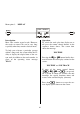
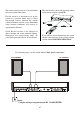
THE CONNECTION TERMINALS OF THE K1 CD-RECEIVER
ANT
AUX / TV
R R R
IN OUT
L L L
TAPE
SUBW
R L
L
R
RC IN
DIGITAL
CD-OUT
250VA
230V~
50-60Hz
SHOCK HAZARD. DO NOT OPEN!
VOR ÖFFNEN DES GERÄTES NETZSTECKER ZIEHEN!
MADE IN GERMANY
FABRIQUE EN ALLEMAGNE
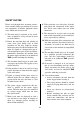
A
B
2 3 5 7 984
6
1
ANT AERIAL INPUT
The system is fitted with a 75 Ω aerial input
socket marked ANT which is designed to
accept a standard domestic aerial. It also ac-
cepts a cable radio connection.
INPUT AUX/TV
A general-purpose pre-amplifier input with
an input resistance of 20 kΩ and a variable
input sensitivity of 160 mV, 250 mV,
400 mV or 600 mV.
Note:
To avoid overload the AUX/TV input should
be set minimum sensitivity 'MIN' (see am-
plifier special function 'SETUP').
IN / OUT TAPE
Input / output sockets for connection to a
machine with recording and playback facili-
ties (recorder).
When you are connecting a recorder note that
the INPUT sockets on the recorder must be
connected to the OUT sockets on the system,
and the OUTPUT sockets on the recorder to
the IN sockets on the system.
SUBW
Output socket to connect an active subwoofer
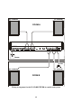
A (Loudspeaker terminals)
Connect the main loudspeakers to this termi-
nals. The impedance of each speaker must
not be lower than 4 Ω.
DIGITAL CD-OUT
Digital output of the internal CD player for
the use of coaxial digital leads.
B (Loudspeaker terminals)
Connect the loudspeakers located in the sec-
ondary room to the
B terminals (Remote
Speakers). The impedance of each speaker
must not be lower than 4 Ω.
Note:
It is important to check that the terminal
clamps are firmly screwed down, and that
there is no chance of short-circuits due to
projecting strands of wire.
Note:
If the loudspeakers are to be used in coun-
tries outside the EU the red/black stoppers
can be removed from the loudspeaker termi-
nals. The speakers can then be connected
using banana plugs.
The stoppers are simply a push-fit in the ter-
minals, and can be prised out from the rear
using a suitable tool such as a knife blade.