OPERATING INSTRUCTIONS DD 1535 R V 1.3 Order No.
Welcome. We are delighted that you have decided to purchase a product. With the addition of the digital surround decoder to your Hi-Fi system you are expanding it to embrace a completely new dimension: Audio-Vision. 1) 2) With the digital surround decoder you can play Dolby Surround, Dolby Digital and dts encoded television programmes, video films and DVDs and experience a genuine “live” atmosphere, complete with exciting sound effects.
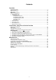
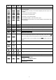
Contents Operation Front panel controls ........................................................................................................................ 4 Remote control ............................................................................................................................... 8 Menu control system ..................................................................................................................... 10 Main menu .....................................................
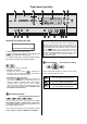
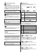
Front panel controls PRO LOGIC IIx DIGITAL DTS OK DD 1535 R ON DVD STB AV VCR TV OTHERS SOUNDFIELD PHONES AMP MENU CAM REC Opening and closing the flap Notes: A form of surround sound can also be obtained with analogue audio devices which are connected to the stereo amplifier or receiver. Select the desired device on your stereo amplifier, and switch the system to Surround mode ( -button).
Display of decoder mode Integral screen PRO LOGIC IIx The display elements of the digital surround decoder are grouped together in a clearly laid out screen: The decoder automatically switches to this mode for any analogue stereo source if it detects that the sound material is Dolby Surround encoded. For digital stereo sources or 2.0 programme material the machine automatically selects PRO LOGIC II if the recorded material permits it. The corresponding LED lights up.
DIGITAL OUTPUT Adjusting screen brightness Digital recording output (optical), designed for connecting a digital recorder temporarily (e. g. for transferring material to a portable MD recorder). The brightness of the alpha-numeric lines of the screen can be set to suit your personal preference by repeatedly pressing the button.
• • VCR recordings with the DD 1535 R (Amplifier Menu) Opening the 'Main Menu'. Pressing this button briefly opens the 'Main Menu'. This is where you can change the surround receiver settings which are only occasionally required in normal daily listening: perhaps to allow for temporary changes in the listening room, or to compensate for unusual characteristics of a special listening source (see 'Main Menu').
Remote control of the Surround Decoder General information In the drawings some of the buttons are filled in ( ); these are the ones which are required for remote control of the decoder. The other buttons have no effect on this unit. The digital surround decoder can be controlled using the F6, F12 remote control handset, or the F1 system remote control unit. If you are using the F1 handset, it must first be switched to Hi-Fi mode.
F1 F12 F6 Switch the handset to Hi-Fi mode.
Menu control system To keep the control panel of the digital surround decoder as compact and uncluttered as possible, the panel does not include dedicated buttons for controlling the decoder functions of tone and level adjustment directly; instead a menu control system ('Main Menu') is used. The following table shows how the menu control system is operated using the remote control buttons, or the buttons on the decoder’s front panel.
Main Menu The 'Main Menu' is designed for adjustments to the decoder which are only occasionally required for daily listening; perhaps to allow for temporary changes in the listening room, or to compensate for unique characteristics of a special listening source. To open the 'Main Menu' press the remote control button or briefly, or the button on the decoder’s front panel.
Sound fields: 2-Channel Mode / 5.1 PL IIx Mode: Disco This sound field is particularly suitable for providing an even spread of sound over a dance area. The sound signal is reproduced with equal power by the main and surround loudspeakers, without echo or delay. The strongly concentrated sound reproduction generates an immediate, energy-charged atmosphere which is a great choice for any party. This menu point enables you to select the decoder for 2channel input signals (e. g. from stereo sources).
Balance left/right and front/surround: Dynamic range: These two menu points allow you to set a temporary change in the balance between the left/right and front/rear loudspeakers, in order to compensate for a temporary listening position which is less than perfect. You can alter the balance in 1 dB increments, and the current value is displayed in the following form: The dynamic range is the difference in volume between the quietest and loudest passages of a recording.
System Configuration This procedure only needs to be carried out when you are installing the system, or when you are adding or replacing individual components of the system. The following diagram shows the menu structure. In the 'Configuration' you can adjust the settings for all the audio and video components of your surround system so that they match each other perfectly, and at the same time set them to suit the acoustic characteristics of your listening room.
Configuration You can call up the 'Configuration' menu by pressing the remote control button or , or the button on the front panel of the decoder; in either case hold the button pressed in for about two seconds. Display brightness: Loudspeaker: The brightness of the screen can be set to suit your personal preference. Three brightness levels are available: The 'Loudspeaker Menu' provides the means to balance the output signals to the loudspeakers in your surround system.
Speaker Setup The three last menu points enable you to adjust the loud-speakers accurately to suit the acoustic and spatial characteristics of your listening room. In the 'Loudspeaker Menu' you can branch off to the menus for setting the loudspeaker size, loudspeaker position, loudspeaker balance and the individual tone settings for each separate loudspeaker.
Speaker size menu To avoid the loss of any sound information in systems where not all the loudspeakers (centre, rear and subwoofer) are present, the missing components must be marked as none in the 'Speaker size menu'. In the 'Speaker size menu' you initially adjust the output signals to suit the existing loudspeaker system. The corresponding sound signal is then distributed over the channels which are present (Downmix). Select menu point Change value Speaker size Main speaker Center speaker Surr.
Back speaker: 5.1 Surnd LS Setting the size and bass capability of the back loudspeakers. The following settings are possible in each case for one (6.1 mode) or two (7.1 mode) rear loudspeakers: As described under 'Surround systems - explanatory notes', the recommended settings for 5.1 loudspeaker sets differ from those for 6.1 / 7.1 speaker sets. To achieve the correct surround effect the surround loudspeakers are located behind the listener for the 5.
Subwoofer: Satellite high pass: In this menu point you set whether a subwoofer is present in your loudspeaker system. Select one of the following settings: Here the lower transition frequency for satellite speakers can be selected. The bass range below the frequency set here (for all loudspeakers whose size is set as 'Satellite') is mixed by the bass manager onto other suitable loudspeakers and the sub-woofer. Bass-manager recommended setting woofer / satellite systems.
Speaker Position Menu This enables the decoder to compensate for timing discrepancies due to differences in speaker location. In the 'Speaker Position Menu' you can enter the distance from the listening position (in 0.3 m increments) for each loudspeaker separately. Recommended loudspeaker arrangement 5.1 Loudspeaker set 7.
Speaker Balance Menu To ensure that the decoder supplies a balanced sound image, the system allows you to adjust the volume of the individual channels to provide a harmoniously balanced arrangement. The purpose of the 'Speaker Balance Menu' is to adjust the level of all the channels. Select menu point Change value -10(dB) . . . 00(dB) . . . +10(dB) -10(dB) . . . 00(dB) . . .
Tone adjust Menu The decoder features an active tone control system (+/6dB) whose purpose is to compensate for the unwanted influence on playback quality of your listening room, or of imperfect loudspeaker positions. The treble / bass balance can be adjusted separately for all the output channels, and can therefore compensate for problems caused by the location of individual speakers.
Auto Setup provides the Auto Setup system as an aid to setting up a surround system correctly. If you follow the steps described below, the DD 1535 R will carry out an automatic calibration of your loudspeakers with the help of the calibration microphone supplied with the set. Under normal listening room conditions this process reliably provides optimum results. The first step is to connect the calibration microphone to the socket marked 'MIC' on the front panel.
Video Inputs menu Every AV source device is connected to one of the AV inputs of the DD 1535 R by means of a Video or S-Video cable, in order to supply picture data to the DD 1535 R. In the 'Video Inputs menu' you determine for each AV input whether the source device connected to it is to operate in normal Video or S-Video mode. Notes: If your device features S-Video outputs, we recommend that you use S-Video mode, as this provides better picture quality.
YUV Inputs menu Some source devices provide picture signals using the high-quality Component Video norm (YUV, YPbPr or YCbCr). If your video monitor features a corresponding Component input, we recommend that you connect all YUVcapable sources using YUV cables in addition *) to the standard Video or S-Video connections. In the YUV Inputs menu you determine which source is connected to which YUV input.
Audio inputs Menu Some source devices also generate a digital output signal, others an analogue multi-channel signal (MCH). Alternative input sockets of the DD 1535 R can be assigned to these source devices; these inputs are suitable for digital signals (co-axial or optical) and multichannel signals. Up to eight AV source devices (with picture and sound signal) can be connected to your surround receiver.
Special Functions menu In the Special Functions menu you can set the following points: TRIGGER 2 / TRIGGER 3 Audio delay for all sources: The back panel of the DD 1535 R features control outputs for automation functions. For example, you can use them to control a motorised screen, so that it extends automatically when you select a video source; alter-natively the light could be dimmed automatically when you select video operations.
Installation Using the system for the first time Safety notes This section describes all those matters which are of fundamental importance when setting up and first using the equipment. This information is not relevant in daily use, but you should nevertheless read and note it before using the equipment for the first time.
Connections DIGITAL INPUT TASI (OPTICAL) Two inputs for digital source devices with optical digital outputs can be assigned to the AV inputs (VCR, SETTOP BOX, DVD, TV AUX AV, CAM) or to the Audio inputs (CD, TAPE, AUX/P) (see 'Inputs Menu'). DIGITAL INPUT Interface for connecting the decoder to a 'R'-series pre-amplifier, integrated amplifier or receiver. The interface automatically switches to surround mode.
SURR (R) and SURR (L) Digital OUTPUT 1) Digital audio signals are present at these sockets for digital recorders or external processors. Terminals for surround loudspeakers In a 5.1 system the right and left rear surround loudspeakers are connected here; in a 7.1 system, the side speakers. Note: Signals are only present here if a digital source device is in use. The outputs are switched off when an analogue source is in use. / Back Rear loudspeaker terminals for 7.1 mode.
TV IN fan Sound input for TV set The fan must never be covered or obstructed by cables. Monitor OUT Picture outputs for video monitor (TV set, projector etc.) with Video or S-Video input. Picture output (Component Video) Additional picture output for video monitor with YUV input. Note: Here only YUV signals are present which are received via one of the YUV inputs () . Video signals or S-Video signals from other AV inputs are not present.
SAFETY NOTES All the components we use meet the currently valid German and European safety norms and standards. This device should never be used without proper supervision. The surround receiver should be set up well out of the reach of small children. This applies to all electrical equipment. Our production areas are supervised by highly qualified expert staff, and all final production units are checked comprehensively by a fully automated, computercontrolled system to ensure uniformly high quality.
Approved usage Device approval and conformity with EC directives This device is designed exclusively for reproducing sound and/or pictures in the domestic environment. It is to be used in a dry indoor room which meets all the recommendations stated in these instructions. In its original condition the unit meets all currently valid German and European regulations. It is approved for use as stipulated within the EC.
Installation, using the unit for the first time General notes on setting up the unit: Note: Carefully unpack the digital surround decoder and store the original packing materials carefully. The carton and packing are specially designed for this unit and will be needed again if you wish to move the equipment at any time. Please be sure to read the safety notes in these instructions.
Notes on connections: • Be sure to push all plugs firmly into their sockets. Loose connections can cause hum and other unwanted noises. • Deploy all mains leads, loudspeaker cables and remote control leads as far as possible from low-level leads (inter-connects) and aerial cables. Never route them over or under the decoder. • Connect the unit to a correctly earthed mains socket using the mains lead supplied.
Connecting the TV set and surround speakers to the decoder: For important information regarding loudspeaker configurations and modes of operation please refer to the chapter 'Loudspeaker configurations for the DD 1535 R'. The components of your system should be connected as shown in Wiring Diagram 1. This is the procedure: • Connect the surround loudspeakers to appropriate output terminals on the decoder. the • If present, connect the input of the active sub-woofer to SUB OUT.
Connecting the decoder to a integrated amplifier with TASI and RLINK socket: To keep the wiring diagram as clear as possible, only the integrated amplifier is shown, i. e. not the analogue source devices. The source devices should be connected as shown in following wiring diagrams. Complete the wiring of the components as shown in wiring diagram as follows: • Please be sure to connect the pre-amplifier output PRE on the pre-amplifier to the sub-woofer input SUB IN on the decoder.
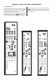
Wiring diagram 1: Connecting the loudspeakers and the TV set to the DD 1535 R Use of banana plugs: see the section entitled 'Back panel connections'. 5.1 Loudspeakerset 6.1 Loudspeakerset 39 7.
Wiring Diagram 2: video monitor with additional Component input 1) additional Component cable for high-quality picture reproduction - select the YUV input on your projector when using DVD (this may have to be done manually if your projector does not feature automatic input signal detection). 2) S-Video connection necessary for playing normal Video and S-Video sources, and video recorder recordings.
DVD player as digital sound and picture source The components of your system should be connected as shown in wiring diagram 3. This is the procedure: • • Connect the digital SURROUND sound output of the DVD player to the digital input (DIGITAL INPUT 3) of the DD 1535 R using a co-axial digital lead. Note: If your DVD player only features a SCART socket, connect it using a SCART / S-Video adaptor. Notes: - Be sure to set the digital output of your DVD player to surround mode.
Wiring diagram 3 * Sound cable between DVD player and stereo amplifier only necessary if the DVD is also to be used for pure twochannel stereo reproduction via the stereo amplifier, or if you wish to use an audio recorder (TAPE) to make sound recordings from the DVD player.
Wiring Diagram 4: a DVD player with YUV Component Video output connected to the DD 1535 R 45
Digital SAT receiver (set-top box) The components of your system should be connected as shown in Wiring Diagram 5. This is the procedure: • If the set-top box features an optical digital sound output, connect it to the digital input (DIGITAL INPUT 1 or 2) of the DD 1535 R using an optical cable. • Settings in the 'Inputs Menu': The digital sound signal of the set-topbox is connected to the optical digital input DIG-1 on the SR 1535 R; to cater for this you should add the name STB as a suffix to DIG-1.
Wiring Diagram 5 47
Recorders (audio devices with record and playback facilities) Analogue recorders Note: It is only possible to record from sources whose analogue sound outputs are connected to the DD 1535 R. If you are using a device with a digital sound output, please be sure to connect the analogue sound output to the input sockets of the DD 1535 R at the same time. The components of your system should be connected as shown in Wiring Diagram 6.
Optimising the system Loudspeaker and signal leads Physical insulation The loudspeaker and signal leads used affect the playback quality of the entire system to an extent which should not be underestimated. therefore recommends the use of high- quality leads and connecting plugs. Tone quality is influenced to a considerable extent by the type of surface and underlying support on which sophisticated HiFi instruments are placed. As far as possible, the surface should be strong, stable, rigid and level.
Surround sound - explanatory notes General information: Types of reproduction The following section is not concerned directly with the operation of your DD 1535 R decoder, but is rather intended to explain some of the terms which arise in connection with surround systems. It is intended to help you understand and exploit the facilities and capabilities of your DD 1535 R to the full.
The surround system This interface is the key to integrating the decoder elegantly into the overall system. At the same time the decoder has absolutely no effect on normal stereo signals, since it is completely removed from the signal path during normal stereo operations. Multi-channel reproduction based on surround technology does indeed open up new worlds of experience, but the technical implementation of a multichannel surround system does involve a number of potential pitfalls.
Dolby Pro Logic IIx Surround Dolby Digital is a digital multi-channel surround system which was developed specifically for spatial sound reproduction in connection with cinema films. The process utilises five separate sound channels: three front channels (left, centre, right) and two surround channels. A sixth independent bass effect channel is also present, catering for low frequency effects (LFE). That is why such systems are said to offer 5.1 channels.
STEREO / MONO mode: dts Digital Surround Stereo The “dts” multi-channel film sound system was originally developed to replace analogue film soundtracks, using digital recordings consisting of six discrete channels. This system has now been further developed to provide spatial sound reproduction in the home situation. Note: A multi-channel signal is converted into a stereo signal (downmix), and reproduced via the main left and right loudspeakers. The six channels (5.
Your DD 1535 R can generate the following sound fields: Sound field simulation The surround processes already described require programme material which is encoded using the appropriate system, but the DD 1535 R also offers a facility to enhance the spatial effect available with conventional unencoded stereo recordings (CD, MC, FM radio etc.). Disco These sound field simulations are based on an accurate analysis of the room acoustics of a number of popular room and hall types.
Dolby Headphone Dolby Headphone is a system which provides a form of spatial sound image even with conventional stereo headphones. Dolby Headphone is a process by which the music signal is processed to simulate the characteristics of music reproduction in a normal room; the result is that an approximation of the usual listening experience is possible even using headphones. Method of working: Dolby Headphone goes even further than this, and incorporates the rear channels which are present in 5.1 / 7.
Loudspeaker configurations for the DD 1535 R To ensure that the SR 1535 R is able to distribute the information in all recordings correctly to your individual loudspeaker combination, it is important that you enter the correct settings in the Loudspeaker Configuration menu when installing your system, i. e. which loudspeakers are present and connected, what size they are, and how far they are located from the listening position.
Auxiliary YUV sockets If your video monitor features a YUV input, you should connect the monitor and all YUV-capable source devices using YUV cables in addition to the Video or S-Video wiring. You can then switch your monitor to YUV mode when using these sources, and in this way obtain the absolute best possible picture quality when watching a film.
Trouble-shooting Many problems have a simple cause and a correspondingly simple solution. The following section describes a few difficulties you may encounter, and the measures you need to take to cure them. If you find it impossible to solve a problem with the help of these notes please disconnect the unit from the mains and ask your authorised specialist dealer for advice. Service Menu The operation of the service menu is similar to the operation of the setup menu (see chapter 'Menu control system').
Problem: Loud humming loudspeakers. noise from the Cause: Poor contact between the Cinch plugs and sockets, or a faulty Cinch cable. Remedy: Please check all connections and cables thoroughly. Problem: No sound, or distorted sound. Cause: Incorrect audio connection to amplifier or TV set. Remedy: Check connections against wiring diagram; push all connectors in firmly. Select a different listening source when checking the amplifier. Problem: No bass, or inadequate bass.
Problem: Neither on-screen menu nor other external programmes appear on the TV screen. TV only shows those stations which are received via its own aerial. Cause 1: Video lead not connected properly. Remedy: Push in all connectors firmly. Cause 2: The TV set does not automatically to the AV input. Remedy: Set the TV set to 'AV operation' mode. Problem: Picture unstable. Cause: Synchronisation signal absent. Remedy: Push connector in firmly, or television to 'AV operation' mode.
Glossary AV source device STANDBY A source device which supplies sound and picture signals. The sound signals may be generated in analogue or digital form. The digital surround decoder can be switched on from stand-by mode at any time by pressing a button on the remote control handset. Center Subwoofer Front loudspeaker between the two main speakers, located below or directly adjacent to the TV set. Loudspeaker designed for reproducing low bass signals.
Specification 5-channel amplifier 7.1 digital decoder 7 2 Type AV inputs Of which recorder max. 8 (TASI) Audio inputs Digital decoder 7.1 Dolby Digital / EX / dts / ES / ES Discrete ProLogic II / ProLogic IIx / dts NEO:6 Dolby headphone 7 Formats Sound field programs Two-channel sound / mono A/D converter (bit / rate) 24 / 48 kHz D/A converter (bit / rate) 24 / 192 kHz 1 Hz – 22 kHz Freq. response THD 0,004 % S:N 106 dB Pre-amplifier 1 Hz – 400 kHz Freq.
elektroakustik GmbH & Co.