
Wiring Guide

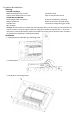
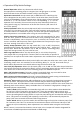

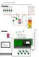

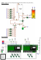


Table Of Contents
- Thermostat Input (24 vac):
- Power Input (120 vac):
- Circulator Output; Zones 1-6 (120 vac):
- Circulator Output; ZR / AUX 1 (120 vac):
- Circulator Output; Primary / AUX 2 (120 vac):
- H Connect the Hot output to Hot power input on circulator.
- Low Limit Aquastat / Tankless Coil Application (120 vac):
- SmartPlus Recirc Logic Sensor
- -Connect the strap-on sensor to the two terminals labeled Recirc Sensor on switching relay.
- SAFETY NOTICE
- TWO SEPARATE sources of power may be connected to an oil boiler’s aquastat control.
- Zone naming
- Programmable output naming
- Alerts & messages
- Post purge time delay adjustment
- Pump exercise time delay adjustment
- Priority protection time delay adjustment
- Indoor boiler reset
- Outdoor boiler reset
- SmartPlus® DHW recirculation logic
- AUX 1 output behavior
- AUX 2 output behavior
- AUX 3 output behavior
- Cooling function
- Zone association
- For your convenience, the Taco Tech Support team is available anytime 24/7. Just call 401-942-8000 for help.

4.
Wiring Procedure:
End Switches (Low Voltage Dry Contacts):
Main
The main end switch closes when any zone thermostat calls for heat and
connects to T-T on boiler operating control.
Priority
The priority end switch closes only when the priority zone thermostat
or aquastat is calling for heat and connects to DHW T-T on boiler (optional).
Thermostat Input (24 vac):
R
Hot side of transformer. Connect to
R
on thermostat.
W
Switched
R
signal from thermostat. Connect to
W
on thermostat.
C
Common side of transformer. Connect to
COM
on
thermostat (optional).
Expansion Connections: (optional)
1 Connect 1 on Master zone control to 1 on all Expansion zone control(s).
2 Connect 2 on Master zone control to 2 on all Expansion zone control(s).
3
Connect 3 on Master zone control to 3 on all Expansion zone control(s).
Power Input (120 vac):
H
Connect to 120 vac Hot side of power supply to zone control.
N
Connect to 120 vac Neutral side of power supply to zone control.
G
Connect ground wire to ground screws on base of zone control.
Circulator Output; Zones 1-6 (120 vac):
H
Connect the Hot output to Hot power input on circulator.
N
Connect the Neutral output to Neutral power input on circulator.
G
Connect ground wire to ground screws on base of zone control.
Circulator Output; ZR / AUX 1 (120 vac):
H
Connect the Hot output to Hot power input on circulator
(or to ZR; see below
).
N
Connect the Neutral output to Neutral power input on circulator.
G
Connect ground wire to ground screws on base of zone control.
Circulator Output; Primary / AUX 2 (120 vac):
H
Connect the Hot output to Hot power input on circulator.
N
Connect the Neutral output to Neutral power input on circulator.
G
Connect ground wire to ground screws on base of zone control.
Low Limit Aquastat / Tankless Coil Application (120 vac):
ZR - H
Connect the Hot ZR (AUX 1) output to ZR input on boiler’s operating control.
ZR -
N
Neutral (optional).
ZC - H
Connect the ZC input to ZC (Hot) output on boiler’s operating control.
ZC - N
Connect (optional).
SmartPlus Recirc Logic Sensor
-
Mount the strap-on sensor on domestic hot water supply pipe on water heater using wire tie or pipe
clamp and insulate sensor with pipe insulation.
-
Connect the strap-on sensor to the two terminals labeled Recirc Sensor on switching relay.
Dedicated Return Line HotLink Valve or Crossover Style Valve
Conceptual Sketches Only, refer to individual manufacture’s installation instructions for additional details. Local codes shall prevail.
For more information on
hot water recirculation
scan QR code
P OW E R IN
120 V AC
N H
(P RIORITY)
ZONE 1
N H N H
ZONE 2
N H
ZONE 3
120 V AC
ZONE IN
N ZC
(AUX 1)
Z R
N H
(AUX 2)
PRI MAR Y
N H
EXPANSION
P 1 2 3
PRIORIT Y
BO I L E R
END
S WI TC H
M AIN
BO I L ER
END
S WI TC H
T STAT 1
T STAT 2
(PR IOR IT Y)
T STAT 3
R W C R W C R W C