
Use and Care Manual


Connecting the LeakBreaker To Your Wireless Network
Before beginning, have the following information available:
a. LeakBreaker Serial Number (located on the inside of the control
panel on the connectors) See Figure B.
b. Network Name (SSID): this is your home’s wireless network
c. Network password (key)
After connecting the power, the unit should show the LED GREEN, but
m flash ORANGE every 3 seconds indicating Wi-Fi setup mode is enabled.
a. The LeakBreaker will remain in this mode for 5 minutes.
b. If 5 minutes passes without connecting to Wi-Fi, your LeakBreaker
will exit the Wi-Fi Setup Mode and no longer be visible to wireless
devices. Press MUTE and OPEN button at same time until you
hear first beep to enter Wi-Fi Setup Mode.
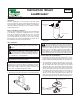
Control Panel and Wiring
Press the tabs on the side of the control panel and pull apart to separate
the front panel from the back panel.
Using the hardware provided, mount the back of the control panel in a
location close enough to the water heater so that both the actuator and
sensor wiring can be connected to the control panel.
If the sensor is to be installed in a metal pan or on a damp surface, insert
the four (4) feet provided into the four (4) holes on the corners of the sen-
sor. (These feet may already be installed.)
With screws on the sensor quick connect facing toward the back of the
controller, plug the sensor wiring into the control panel port marked sen-
sor. Place the sensor on the floor, at the base of the water heater, making
sure it is located where water is likely to flow in the event of a leak. If the
water heater is in a pan, place the sensor inside of the pan. If additional
sensors were purchased, locate them in different areas around the water
heater.
With the screws on the actuator quick connect facing toward the back of
the controller, plug the actuator wiring into the control panel port marked
valve.
Two (2) sets of dry contacts are provided. Each set includes normally open
and normally closed connections. They can be used to send a signal to
any device requiring an open or closed signal, such as a security system.
If using batteries, install them into the battery holder. Be sure to insert
each battery in the correct orientation as indicated in the battery holder. If
electrical power is being used the power cord may also be connected.
LeakBreaker can be powered by batteries, power supply or both.
LeakBreaker with eLink must use AC power supply. This model is
equipped with optional battery back up.
Assemble the front on the control panel to the back of the panel.
If your LeakBreaker features eLink™, continue with the steps below
immediately after installation to setup Wi-Fi
®
and register your device to
enable notifications
NOTE: When attaching the wires to the actuator quick
connect, the black wire must match up to the "B" on the
control and the red wire must match up to the "R" on the
control. The LeakBreaker will not function correctly if
it is not wired correctly.
1.
2.
5. 6.
1.
2.
3.
6.
7.
1.
2.
5.
4.
Fig. B
4.
3.
2
NOTE: LeakBreakers without eLink, continue to “Testing Your Installation” on page 4.
ATTENTION: eLink setup instructions continue on page 3. You must com-
plete all of the required steps in order to connect your device and start
receiving status change alerts!
ATTENTION: When using the LeakBreaker with
eLink, AC power must be used. Battery back up is an
available option. Wireless functionality shortens
battery life significantly if AC power is not used!
NOTE: Make sure valve and sensor are plugged in
first. If not, follow instructions for control panel
and wiring. Double check that your device is con-
nected to power before proceeding with eLink
setup.
Continue below to setup eLink functionality (For model: LBW-XXX-X-XXX)
Wi-Fi
®
is a registered trademark of Wi-Fi Alliance
®.