
Use and Care Manual
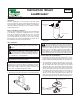


The first sensor (A) will have its wire leads go directly from the sensor board A’s terminal block to the sensor input on the control panel.
The next sensor (B) will have its wire leads go from the sensor board B’s terminal block to the terminal block on the first sensor board (A).
The next sensor (C) will have its wire leads go from the sensor board’s (C) terminal block to the terminal block on the second sensor
board (B).
The first (A) and second (B) sensors will have their end tab
removed.
The last sensor (C) in the chain will still have its end tab attached.
CLOSE
OPEN
Front panel
Press
Open
Testing Your Installation
Press the open button on the front panel to open the valve, watch the indicator on the top
of the valve to make sure the valve rotates to the open position, press the close button to
close the valve and watch the indicator on the top of the valve to make sure the valve
rotates to the closed position.
Close any open fixtures and open any shut-off valves that were closed during the installa-
tion of the valve. Make sure there are no leaks.
With the valve in the open position place the sensor in water. The valve should close, the
LED should flash red and the audible alarm should sound. Once the valve closes, press
the mute button to silence the alarm.
a.
To reset the LeakBreaker, completely dry off the sensor and then press the open button.
1.
2.
3.
4.
Press
Close
Congratulations on the successful installation of your LeakBreaker!
4
Installing Additional Sensors
Up to ten (10) sensors may be daisy chained to the sensor input with a total wire
length of no more than 200 feet.
Tab Configuration for Multiple Sensors
The last sensor in any chain must be the only one with the “tab” still attached. Reference
Figure E to break off tab. Reminder: remove and replace feet from broken tab to the sensor.
Broken tab can be discarded; it cannot be reattached in the future.
1
1
2
2
1
1
2
2
1 2
CLOSE
OPEN
AB
C
Fig. E
1
1
2
2
1
1
2
2
AB
NOTE: Terminal A1 wires to Terminal B1. Terminal B1 wires to
Terminal C1.
Tab stays connected here
Wiring of Multiple Sensors (Example description is for a three (3) sensor chain.)
NOTE: The last sensor in the chain (furthest from the controller) must
keep its tab.
If using the LeakBreaker with eLink, when the valve is triggered, a text
notification should be sent to your phone and/or email with the following
message, "TACO LEAKBREAKER ALERT: Sensor has detected water.
Alarm has triggered. Valve has been closed."