
Install Instructions

Instruction Sheet
0015-MSF-IFC Multi-Speed Cartridge Circulator
with Integral Flow Check
102-433
APPLICATION:
• Maximum operating pressure is 125 psi (862 kPa).
• Maximum water temperature not to exceed nameplate rating.
• Cast iron circulators are to be used for closed loop systems only.
• Stainless steel circulators are to be used on open, potable water systems.
• Taco Cartridge circulator pumps are for indoor use only – employer uniquement a
l´interieur.
• For use with water or maximum of 50% glycol/water mix systems only.
CAUTION: 1. The addition of petroleum based fluids or certain chemical additives to systems
utilizing TACO equipment voids the warranty.
2. Use supply wires suitable for 90°C – ATTENTION: Employer des fils d´alimentation
adequats pour 90°C.
WARNING: To avoid electrical shock, disconnect the power supply to the circulator and the main
electrical unit.
WARNING: Do not use in swimming pool or spa areas; pump has not been investigated for this
application.
WARNING: In the event the electrical box has been pulled off of the housing, DO NOT attempt to
reattach it. Use of any other screw may short out the stator windings, creating a risk of
electrical shock.
CAUTION: When installing electrical connections, do not apply mechanical loads to the capacitor
box; otherwise, retaining screws may be pulled out of the housing, making circulator
unusable.
S
UPERSEDES: June 1, 2014 EFFECTIVE: August 10, 2015
Plant ID# 001-4002
CAUTION: Installations at higher elevations over 5000 feet must have higher fill pressure of 20 psi
minimum to prevent pump cavitation and flashing. Premature failure may result. Adjust
expansion tank pressure to equal fill pressure. A larger size expansion tank may be required.
INSTALLATION:
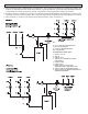
1. Location – Install the
“OO” circulator on the supply side of the boiler “pumping away” from the expansion tank as shown in
Figure 1. This is the best pump location for optimum system performance and maintaining positive system pressure. An alter-
nate location is on the boiler return line as shown in Figure 2.
2. Mounting position – Mount circulator with the motor in the horizontal position. It may be mounted vertically with the
motor up, provided that the system cold fill pressure is at least 20 psi (138 kPa) to ensure proper air purging and prevent
flashing.
3. Rotating body – Body has an arrow on the front that indicates direction of flow. To rotate body, remove the four body
bolts, rotate body and replace bolts. Make sure that the junction box is NOT located underneath the circulator. (The
junction box must NOT be located in the 6 o’clock position, as viewed from the motor end.)
4. Electrical connections – Observe all applicable codes when connecting to power supply.
The motor is thermally protected, and does not require additional overload protection.
Either colored wire from the capacitor box can be attached to either colored wire from the
power supply. There is no “hot” or “common” wire leading from the capacitor box. Typical
installation would be to attach the white wire to the white (common) power supply wire and
either the yellow or blue wire to the black (hot) power supply wire. The pump cannot run
backwards.
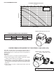
SPEED
Amps (Watts)
1 0.54 (58)
2 0.74 (79)
3 0.85 (98)
ELECTRICAL DATA
CAUTION: Do not use flat rubber gaskets on pump flanges. Only use O-ring gaskets provided or
leaking will result. Warranty will be void.