
Selecting Circulators Guide


TD10 – 5
SOME FINAL POINTS
In addition to selecting a circulator that produces a flow equal to or slightly above the target value, other factors should
be considered:
1. To achieve reasonable wire-to-water efficiency the target operating point should fall within the middle third of the flow
rate range covered by pump curve for the selected circulator. It’s not good practice to select a circulator where the
target operating point falls near the outer ends of the pump curve, even if the pump curve is still above the target operat-
ing point. Doing so would force the circulator to operate at relatively low efficiencies that increase system operating cost.
2. In systems using zone valves (or manifold valve actuators) select a circulator with a relatively flat pump curve.This min-
imizes changes in differential pressure as the zone valves open and close. (See TD01, When Zone Valves Close, for addi-
tional information.)
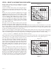
3. In systems having a high flow rate and low head loss
requirements consider using two smaller circulators in
parallel rather than a single larger circulator. The “effec-
tive” pump curve for two identical circulators in parallel is
found by doubling the flow rate at every value of head. In
effect the pump curve of a single circulator is “stretched
out” to twice its length along the horizontal axis as shown
in Figure 3.
If two or more circulators are used in parallel, be sure to
include a check valve downstream of each circulator to
prevent reverse flow should one circulator be inoperable.
4. Be very careful when selecting circulators with steep
pump curves for use in high temperature systems. The
potential for vaporous cavitation within the circulator is
higher in such situations. Avoiding cavitation will require
higher static pressures.
This article has outlined the steps that hydronic system designers can follow to select an appropriate circulator for a given
piping system. In many cases, two or more circulator options can each yield acceptable performance based on tradeoffs
in system piping. A good selection addresses the total owning and operating cost of the system (circulator and piping)
over its design life rather than just first cost. Excessive oversizing of circulators increases initial as well as life cycle costs and
should be avoided.The wide range of hydronic circulators available from Taco allows conscientious designers to properly
match the circulator to the task.
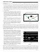
5. When selecting components for a system, it is worth not-
ing the effect that their imparted resistance has on pump
performance. It may be one thing to see the final number
that is calculated as part of establishing the head loss of
the piping system, but how does that number actually
effect the flow rate in the system? This becomes very clear
when comparing a system where a conventional weighted
flow check is installed versus a pump with an integral flow
check (00-IFC), as illustrated in Figure 4.
Shown is the 008 circulator, but this example holds true for
any model.When a common Taco Model 219,
3
⁄
4
" Flo-Chek
is installed along with the pump the imparted resistance
shifts the pump curve down and to the left as illustrated.
The hydraulics of the 00 Circulators with Integral Flow
Checks (00-IFC) has been specifically engineered to mini-
mize the total impact of the built-in flow check, hence the
smaller pump curve shift. Just the difference of using a
008-IFC versus a standard 008 can be seen in the flow
output of the circulator at a given head loss.
Example 5: If you had a system with 10 feet of head loss, you would expect to get 8 gpm of flow in the system. Say you
forgot to add in a flow check to prevent gravity flow. If you were to add a 219,
3
⁄
4
" Flo-Chek, all of a sudden you would
have a flow rate of 2 gpm through the same system. If you decided to install a 00-IFC instead of the in-line flow check,
the flow would be just over 7 GPM.The selection of components, correct figuring of total system head loss, and match-
ing the target operating point with the appropriate circulator can have a major impact on the performance of a system.
0
2
4
6
8
10
12
14
16
18
0
2 4681012 14 16 18 20 22 24 26 28 30 32 34 36 38 40
head added / loss (feet)
system head loss curve
"effective" pump curve for two circulators in parallel
pump curve for single circulator
Figure 3
0
0
1234567 8
Flow (gpm)
9101112131415
16
15
14
13
12
11
9
10
8
7
6
5
4
3
2
1
Head (ft)
008-F6 w/TACO
219 Flo-Chek
008-F6 IFC
008-F6
Figure 4