
00 Series Zoning Circulator Pump Instruction Manual

Instruction Sheet
Priority Zoning Circulator
102-070A
SUPERSEDES: November 1, 2006 Patent No. 5,622,221 EFFECTIVE: May 1, 2010
Plant I.D. 001-3901
Description:
The Taco Priority Zoning Circulator combines the reliability of
the “00” circulator with the convenience and efficiency of a PC
board mounted switching relay package. Each Zoning
Circulator has a built-in Priority Switch mounted directly on the
PC board. The priority switch allows the installer to choose the
zone that requires the most priority, and when activated only
that circulator will run. The Priority Zoning Circulator can be
used in conjunction with circulators or zone valves. It is com-
patible with electronic digital thermostats.
Application:
Hydronic systems that require the installer to choose one
zone that has priority over all other zones.
• Indirect hot water heaters.
• Zoning with circulators.
• Add a zone to existing heating systems.
• Under-sized zones that never come up to heat can now
be switched to first priority.
Installation:
FOLLOW ALL INSTRUCTIONS IN THE SEQUENCE THAT
THEY APPEAR.
Basic “00” Circulator Installation Instructions
1. Refer to instruction sheet number 102-054 for all basic
circulator application/installation instructions packed
separately in the Priority Zoning Circulator box.
Priority Switch:
1. All Priority Zoning Circulators are shipped
with the priority switch in the “MASTER”
position.
2. When using the priority feature, leave the
priority zone circulator in the “MASTER”
position, and switch the non-priority circu-
lators to the “OFF” position. A maximum of
1 priority “00” circulator and 3 non-priority
“00” circulators can be connected together.
Priority Zoning Circulator Operation:
1. Priority circulator thermostat calls for heat.
2. The Priority circulator turns “ON”.
3. The Non-Priority circulators turn “OFF”.
4. The dry contact switch to the boiler control closes allow-
ing the boiler to operate.
Electrical Hook-Up:
1. All electrical work must be performed by an electrician in
accordance with the latest edition of the National
Electrical Codes and Local Codes and Regulations.
2. Disconnect all Electrical Power.
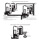
3. Wiring Connections: Follow Basic Priority Zoning
Circulator Wiring Diagrams.
Terminals R & W: Maximum 24VAC
Thermostat – Connect terminals R and W to the individual
room thermostat or aquastat control.
Terminals X & X: Maximum 24VAC 3AMP
Relay-Contact – Connect terminals X and X to “TT” on boil-
er controls.
Terminals R & C: Optional for 24VAC Output (0.5VA max)
(off)
MASTER
RWXXRC
LOW VOLTAGE
TERMINAL STRIP
MASTER
(on)
WARNING: Do not use in swimming pool or spa areas;
pump has not been investigated for this
application.
WARNING: In the event the retaining screws have been
pulled out of the housing, DO NOT replace
them. Use of any other screw may short out the
stator windings, creating a risk of electrical
shock.
WARNING: To avoid electrical shock, disconnect the power
supply to the circulator and the main electrical
unit.
CAUTION: When installing electrical connections, do not
apply mechanical loads to the capacitor box;
otherwise, retaining screws may be pulled out
of the housing, making circulator unusable.
CAUTION: Installations at higher elevations over 5000
feet must have higher fill pressure of 20 psi
minimum to prevent pump cavitation and
flashing. Premature failure may result. Adjust
expansion tank pressure to equal fill pressure.
A larger size expansion tank may be required.
CAUTION: 1. The addition of petroleum based fluids or
certain chemical additives to systems utilizing
TACO equipment voids the warranty.
2. Use supply wires suitable for 90°C – ATTEN-
TION: Employer des fils d´alimentation ade-
quats pour 90°C.