
Install Instructions


Minimum Variable Speed Output
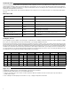
When the 00-VDT is configured for reverse acting mode (ΔT operation), a minimum variable
speed ouput is incorporated during operation to insure proper flow across both sensors. In
this case, the variable speed output is adjusted between the selected minimum variable
speed output percentage and full output. Depending on the amount of system resistance
in your application, select the preferred minimum variable speed output from the table to
the right. The 00-VDT also provides full output for 30 seconds when the Heat Request
appears, then resumes normal operation.
Note: Minimum variable speed output is not available when configured for Direct Acting Mode (DIP switch 3 set to Off).
Pump Start-up
When the 00-VDT is powered up, the circulator operates at full speed for 30 seconds before varying its speed anywhere between min-
imum and full speed as required to maintain the selected differential temperature.
In Direct Acting Mode (DIP switch 3 = Off) the speed of the circulator will ramp up as required to maintain the selected differential
temperature.
Exercising
Every 72 hours of no operation, the 00-VDT is designed to exercise for 10 seconds in order to prevent precipitate build-up in the pump.
The % OUT LED turns on during the exercising function.
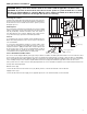
Sequence of Operation
Power Up and Heat Request
Whenever the 00-VDT is powered up, the green PWR LED turns on. The 00-VDT starts operating once a heat request signal is present
at the Heat Request (Ht Req) terminals. The heat request terminals come factory jumpered so the pump will start as soon as it is pow-
ered up. The jumper may be removed and a heat request signal may be provided by external end switches from zone valves or Taco
ZVC/SR series zone controls, applying a dry contact closure or a powered 24 V (ac) signal across the Ht Req terminals. Once a heat
request signal is present, the green HEAT REQ LED turns on.
Delta T Setting and Operation
Once a heat request is present, the 00-VDT operates to provide a fixed ΔT between the supply
sensor (S2) and the return sensor (S1). The fixed ΔT is set using the RANGE dial, where 5°F and
50°F corresponds to 1 and 10 respectively on the RANGE dial, with the temperature increasing
in 5°F increments. The percent output (% OUT) LED flashes at different rates based on the speed
of the pump.
Dip Switch Settings
2
1
2
3
8
4
5
6
7
9
1
0
RANGE
5
º
1
0
º
F
1
5
º
F
4
0
º
F
2
0
º
F
º
F
º
F
35
º
F
4
5
º
F
50
º
F
T
DIP Switch 1: T Operation = On
DIP Switch 2: Minimum Speed = Off or On
DIP Switch 3: Mode of Operation = On
DIP Switch 4: Output Response = Off
DIP Switch 5: Output Characteristic = Off or On
DIP switch 2 = Off DIP switch 2 = On
Minimum Variable Speed Output
Normal (default) Lower
Pump Selection
The circulator should be sized, using conventional sizing practices, based on the required head and flow for the system or zone on
which the circulator is being installed.