
Install Instructions


3
Wiring and Sensor Installation
Powering the Control
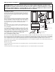
Insert the line voltage wires through the knockout of the enclosure
and connect the live wire to the H terminal and the neutral wire to
the N terminal on the PC Board. Ensure that no power is present
during this process.
Heat Request
The heat request signal may be provided by the factory installed
jumper or the jumper can be removed and a heat request signal
may be provided by external end switches from zone valves or
Taco ZVC/SR series zone controls, applying a dry contact closure
or a powered 24 V (ac) signal across the Ht Req terminals.
Sensors
Do not apply power to these terminals as this will damage the PC
Board. The wiring terminals for the sensors may be removed for
ease of installation.
Do not run the wires parallel to telephone or power cables. If the
sensor wires are located in an area with strong sources of electro-
magnetic interference (EMI), shielded cable or twisted pair should
be used or the wires can be run in a grounded metal conduit. If
using shielded cable, the shield wire should be connected to the
Com terminal on the PC Board and not to earth ground.
Sensor Installation and Placement
The sensors can be strapped directly to the pipe using a cable tie. Insulation should be placed around the sensor to reduce the effect
of air currents on the sensor measurement. The sensors should be placed downstream of a pump or after an elbow or similar fitting.
This is especially important if large diameter pipes are used because the thermal stratifcation within the pipe can result in erroneous
sensor readings. Proper sensor location requires that the fluid is thoroughly mixed within the pipe before it reaches the sensor.
If the system sensor is used to measure duct (air) temperature, the sensor should be mounted in such a manner that it measures the
average duct outlet temperature.
Return Sensor (S1)
Connect the two wires from the return sensor (S1) directly into the Com and S1 terminals on the PC Board.
Supply Sensor (S2)
Connect the two wires from the supply sensor (S2) directly into the Com and S2 terminals on the PC Board.
WARNING: Wiring connections must be made in accordance with all applicable electrical codes.
CAUTION: To prevent electrical shock, disconnect electric power to system at main fuse or circuit
breaker box until installation is complete. When a service switch is installed, more than one discon-
nect switch may be required to deenergize this device for servicing.
S3
N
H
S2 S1 Com
Power: 120 V ±10%
900 VA 60 Hz
Var. Speed: 120 V
(ac) 2.4 A 1/6 hp
Ht
Req
Ht
Req
Made in
Canada
MOV
T2.
5A
2
50V
co
i
l
f
use
0.1µF
R
Y
XFMR
Factory Installed Jumper
or
End Switch
Supply
Sensor (S2)
Return
Sensor (S1)
N
120 V (ac)
H
To ground screw
on PCB enclosure
0.1µF