
Install Instructions


4
Troubleshooting
As in any troubleshooting procedure, it is important to isolate a problem as much as possible before proceeding. The error messages
greatly simplify troubleshooting of the 00-VDT. When the 00-VDT flashes an error message, identify the fault and follow standard test-
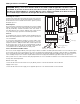
ing procedures to confirm the problem. If you suspect a wiring fault, return to the wiring section on this brochure and carefully check
all external wiring and wiring connections.
For your safety and protection from permanent damage to the microprocessor, the 00-VDT includes a 2.5 A (250 VAC) field replace-
able fuse.
Multi-Status LED
Testing the Sensors
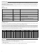
A good quality test meter capable of measuring up to 5,000 kΩ (1 kΩ = 1000Ω) is required to measure the sensor resistance. In addi-
tion to this, the actual temperature must be measured with a good quality digital thermometer.
First measure the temperature using the thermometer and then measure the resistance of the sensor at the 00-VDT. The wires from the
sensor must not be connected to the PC Board while this test is performed. The wiring terminals are easily removed by pulling them
from the PC Board. Using the chart below, estimate the temperature measured by the sensor. The sensor and thermometer readings
should be close. If the test meter reads a very high resistance, there may be a broken wire, a poor wiring connection or a defective sen-
sor. If the resistance is very low, the wiring may be shorted, there may be moisture in the sensor or the sensor may be defective. To test
for a defective sensor, measure the resistance directly at the sensor location.
Temperature
Resistance Temperature Resistance Temperature Resistance Temperature Resistance
°F °C
Ω
°F °C
Ω
°F °C
Ω
°F °C
Ω
-30 -34
234,196 30 -1 34,558 90 32 7,334 150 66 2,045
-20 -29 165,180 40 4 26,099 100 38 5,828 160 71 1,689
-10 -23 118,018 50 10 19,900 110 43 4,665 170 77 1,403
0 -18 85,362 60 16 15,311 120 49 3,760 180 82 1,172
10 -12
62,465 70 21 11,883 130 54 3,050 190 88 983
20 -7
46,218 80 27 9,299 140 60 2,490 200 93 829
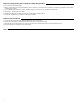
LED LED Status OO-VDT Status
PWR Solid Power On
HEAT REQ Solid Heat Request
% OUT Flash (Solid) Variable Speed Output
HEAT REQ Flash
System Sensor S1 Fault.
00-VDT does not operate.
RED OUT Flash
System Sensor S2 Fault.
00-VDT does not operate.
HEAT REQ and RED OUT Flash
Boiler Sensor S3 Fault. No sensor should be connected to
S3. 00-VDT does not provide boiler protection.
POWER, HEAT REQ and RED OUT Flash
No sensors connected, or incompatible mode and sensor
combination.
Application
1. Maximum operating pressure: 125 psi (862 kPa) on all “00” Series Circulators.
2. Maximum water temperature not to exceed nameplate rating.
3. Cast iron circulators are to be used for closed loop systems. Bronze circulators are to be used for open loop, fresh water, or
potable water systems.
4. Taco Cartridge circulator pumps are for indoor use only – employer uniquement a l´interieur.