
Install Instructions


In order to properly accomplish this mixing method, the follow-
ing piping details should be considered.
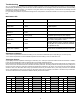
When the injection pump is turned off, there must be no heat
transfer from the boiler loop to the system loop. In order to
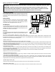
avoid this unwanted heat transfer, primary/secondary piping
techniques are used as shown in figure 1.
This piping arrangement requires that the injection piping be
at least one pipe diameter smaller than the piping of the boiler
and system loops. There must be no more than 4 pipe diam-
eters between the tees in the boiler and system loops (Note
1), in order to prevent ghost flow when the injection pump is
off and the system or boiler pump is on. Also, there must be at
least 6 pipe diameters of straight pipe on either side of the tees
(Note 2), in order to prevent the momentum of water from the
boiler and system loops from pushing flow through the injection
loop. Finally, there should be a minimum of 1 foot drop in the
injection loop in order to create a thermal trap (Note 3) in order
to prevent convective heat transfer through the injection loop.
Design Procedure
In order to properly size the pump, follow the design procedure below:
1) Determine the design operating temperatures of the system loop and boiler. (Ts and Tb from figure 1)
2) Determine the flow rate and design temperature drop (ΔT - Delta T) in the system loop. If one of these variables is unknown use
Equation 1 or 2 to calculate the other variable.
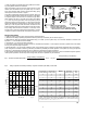
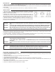
3) Compute Tb - Ts. Look up the ratios in figure 2.
4) The design injection flow rate for direct injection is calculated from Equation 3. If the injection flow rate is greater than 40 US GPM,
a 3-way or 4-way valve may be required.
5) Decide whether or not to include a balancing valve in the injection piping. A balancing valve allows adjustment when the injection
pump is larger than needed. A balancing valve also provides the possibility of manual operation of the system by turning the injection
pump fully on and adjusting the balancing valve to obtain the desired supply water temperature.
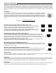
6) The injection piping size and model of Taco 00 pump to install can now be looked up in figure 3. Do not oversize the injection system.
If the injection system is not able to provide enough heat, the boiler’s aquastat may be increased.
Eq.1: Eq. 2:
Eq.3:
System Flow Rate (US GPM) =
Design Heating Load (BTU/hr)
500 x Δ Ts (°F)
ΔT (°F) =
Design Heating Load (BTU/hr)
500 x System Flow Rate (US GPM)
Design Injection Flow Rate (US GPM) = System Flow Rate (US GPM) x Flow Ratio
2
Gjh/!2
Cbmbodjoh
Wbmwf
Cpjmfs
Mppq
Tztufn
Mppq
)Ut*
)Uc*
11.WS
!Jokfdujpo!Qvnq
EUt
Uc >!!Cpjmfs!tvqqmz!ufnqfsbuvsf
Ut >!!Tztufn!tvqqmz!ufnqfsbuvsf
EUt >!!Tztufn!ufnqfsbuvsf!espq!)Uzqjdbmmz!31±G!gps
dpowfdupst!boe!21±G!gps!sbejbou!gmpps!ifbujoh*
Opuf!4
Opuf!2
Opuf!3
Opuf!4
Opuf!2
Opuf!3
Tb - Ts (°F)
Ts (
°
F
)
0.40
0.0
0.2
1.00
0.8
0.60
10 30 50
70
90
Fig. 2
10
15
20
25
Flow Ratio
20
40 60 80
0.1
0.3
0.50
0.70
0.9
Nominal Pi
p
e
Diameter (inches
)
TAC
O
Pum
p
This table assumes there are 5 feet of pipe, 4 elbows, and 4 branch tees of the listed diameter
.
B
alancin
g
valve is assumed to be a ball valve. The approximate Cv value is provided in order
to allow for proper balancin
g
device. Valve characteristics ma
y
var
y
for the same size and t
y
pe
o
f
ba
ll v
a
lv
e
fr
o
mm
a
n
u
f
ac
t
u
r
e
r t
o
m
a
n
u
f
ac
t
u
r
e
r
.
Balancin
g
V
a
lv
e
C
v
Balancin
g
Valv
e
Position
(
% open
)
Desi
g
nIn
j
ectio
n
Flow Rate
(
US GPM
)
20
30
25
4
0
4
0
2
00
1
2
00
1
2
00
1
0
00
1
0
00
1
0
00
1
0
007
007
007
007
006
2
1
1
1
1.
5
1
0
.7
5
0
.7
5
0
.
5
1.2
5
3
4.
2
1
8
.
2
28
.
8
1
9
.
8
1
0
.
8
1
0
.
8
1
0
.
4
6
.
9
1
5
5
.7
6
36
30
50
5
0
10
0
50
4
0
4
0
4
0
1
00
30
1
6
1
4
1
2
9
7
8
4
003
0
.
5
2
.4
30
1.
5
2
003
0
.
5
4.
5
4
0
3
006
0
.
5
4.
5
4
0