
Install Instructions


Wiring and Sensor Installation
WARNING: Wiring connections must be made in accordance with all applicable electrical codes.
CAUTION: To prevent electrical shock, disconnect electric power to system at main fuse or
circuit breaker box until installation is complete. When a service switch is installed, more than
one disconnect switch may be required to deenergize this device for servicing.
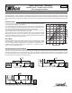
Powering the Control
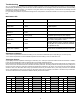
Insert the line voltage wires through the knockout of the enclosure
and connect the live wire to the H terminal and the neutral wire to the
N terminal on the PC board. Ensure that no power is present during
this process.
System Pump
The 00-VR includes a 5 amp relay in order to operate the system
pump. Connect one of the wires of the system pump to the PMP
terminal on the control. The other wire on the system pump must be
connected to the neutral (N) side of the 120 V (ac).
Heat Request
The heat request signal may be provided by jumpering the heat
request (Ht Req) terminals or by applying 24 V (ac) to the Ht Req
terminals. This signal may come from zone valve end switches, Taco
ZVC/SR zone controls, or thermostats.
Sensors
Do not apply power to these terminals as this will damage the control.
The wiring terminals for the sensors may be removed for ease of
installation.
Do not run the wires parallel to telephone or power cables. If the
sensor wires are located in an area with strong sources of electromagnetic interference (EMI), shielded cable or twisted pair should
be used or the wires can be run in a grounded metal conduit. If using shielded cable, the shield wire should be connected to the Com
terminal on the PC board and not to earth ground.
Outdoor Sensor (S1)
Remove the screw and pull the front cover off the outdoor sensor enclosure.
The sensor can either be mounted directly onto a wall or in a 2” x 4” electrical box. When the sensor is wall mounted, the wiring should
enter through the back or bottom of the enclosure. Do not mount the sensor with the conduit knockout facing upwards as rain could
enter the enclosure and damage the sensor.
In order to prevent heat transmitted through the wall from affecting the sensor reading, it may be necessary to install an insulating
barrier behind the enclosure.
The sensor should be mounted on a wall which best represents the heat load on the building (a northern wall for most buildings and
a southern facing wall for buildings with large south facing glass areas). The outdoor sensor should not be exposed to heat sources
such as ventilation or window openings.
Connect 18 AWG or similar wire from the outdoor sensor directly into the Com and S1 terminals on the PC board.
Replace the front cover of the sensor enclosure.
Supply and Boiler Return Sensors
The sensors can be strapped directly to the pipe using a cable tie. Insulation should be placed around the sensor to reduce the effect
of air currents on the sensor measurement.
The sensors should be placed downstream of a pump or after an elbow or similar fitting. This is especially important if large diameter
pipes are used because the thermal stratification within the pipe can result in erroneous sensor readings. Proper sensor location
requires that the fluid is thoroughly mixed within the pipe before it reaches the sensor.
System Supply Sensor (S2)
Connect the two wires from the supply sensor directly into the Com and S2 terminals on the PC board.
Boiler Return Sensor (S3)
Connect the two wires from the boiler return sensor directly into the Com and S3 terminals on the PC board.
4
231!W!)bd*!boe
Tztufn!Qvnq
up!kvodujpo!cpy
FoeTxjudi
Pvuepps!Tfotps
Tvqqmz
Tfotps
Cpjmfs!Sfuvso
Tfotps
Qpxfs;!231!W!,0.!21&
:11!WB!71!I{
Wbs/!Tqffe;!231!W
)bd*!3/5!B-!207!iq
Qnq;!231!W!)bd*!6!B
207!iq
WT
Dbq
):47
Dbq
):47
Dbq
):47.
O
I
Nbef!jo
Dbobeb
T4 T3 T2
Dpn
Iu
Sfr
Iu
Sfr
QNQ
Up
hspvoe