
Install Instructions


Ufnqfsbuvsf Sftjtubodf Ufnqfsbuvsf Sftjtubodf Ufnqfsbuvsf Sftjtubodf Ufnqfsbuvsf Sftjtubodf
±G ±D
X
±G ±D ±G ±D ±G ±D
.41
.31
.21
1
21
31
41
51
61
71
81
91
:1
211
221
231
241
251
261
271
281
291
2:1
311
.45
.3:
.34
.29
.23
.8
.2
5
21
27
32
38
43
49
54
5:
65
71
77
82
88
93
99
:4
345-2:7
276-291
229-129
96-473
73-576
57-329
45-669
37-1::
2:-:11
26-422
22-994
:-3::
8-445
6-939
5-776
4-871
4-161
3-5:1
3-156
2-79:
2-514
2-283
:94
93:
XXX
5
Troubleshooting
As in any troubleshooting procedure, it is important to isolate a problem as much as possible before proceeding. The error messages
greatly simplify troubleshooting of the 00-VR. When the 00-VR flashes an error message, identify the fault and follow standard testing
procedures to confirm the problem. If you suspect a wiring fault, return to the wiring section on this brochure and carefully check all
external wiring and wiring connections.
For your safety and protection of permanent damage to the microprocessor, the 00-VR includes a 2.5 A 250 V (ac) field replaceable
fuse.
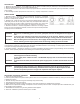
Multi-Status LED
Adjustment of Settings
- If the outdoor temperature is cold and the building is cold, increase the Reset Ratio (Curve dial) setting by one notch per day.
- If the outdoor temperature is near the WWSD temperature and the building is cold, turn DIP switch 5 on.
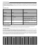
Testing the Sensors
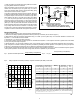
A good quality test meter capable of measuring up to 5000 kΩ (1 kΩ = 1000 Ω) is required to measure the sensor resistance. In addition
to this, the actual temperature must be measured with a good quality digital thermometer.
First measure the temperature using the thermometer and then measure the resistance of the sensor at the 00-VR. The wires from the
sensor must not be connected to the PC board while the test is performed. The wiring terminals are easily removed by pulling them
from the PC board. Using the chart below, estimate the temperature measured by the sensor. The sensor and thermometer readings
should be close. If the test meter reads a very high resistance, there may be a broken wire, a poor wiring connection or a defective
sensor. If the resistance is very low, the wiring may be shorted, there may be moisture in the sensor or the sensor may be defective.
To test for a defective sensor, measure the resistance directly at the sensor location.
MFE MFE!Tubuvt 11.WS!Tubuvt
QXS Tpmje Qpxfs!Po
IFBU!SFR Tpmje Ifbu!Sfrvftu
XXTE Tpmje Xbsn!Xfbuifs!Tivu!Epxo
IFBU!SFR
Gmbti
Pvuepps!Tfotps!gbvmu/!Uif!11.WS!bttvnft
bo!pvuepps!ufnqfsbuvsf!pg!43±G/
SFE!PVU
Tpmje
Sfevdfe!Pvuqvu!)Cpjmfs!Qspufdujpo!Bdujwbufe*
&!PVU
Gmbti!)Tpmje* Wbsjbcmf!Tqffe!Pvuqvu!)211&!Tqffe*
XXTE
Gmbti
Tvqqmz!Tfotps!Gbvmu/!Jg!b!tztufn!nbyjnvn
jt!tfu!)EJQ!2!'!3*-!uif!11.WS!uvsot!pgg-!puifsxjtf
ju!pqfsbuft!bu!21&/
IFBU!SFR!'!XXTE
Gmbti
Cpjmfs!Tfotps!Gbvmu/!Cpjmfs!qspufdujpo!jt!jhopsfe/