
Manual


This article shows you how to select a Taco circulator that lets the hydronic system you’re designing perform as expected.
The process requires that you first define the flow performance of the piping system.After this, you will match the sys-
tem’s performance requirements with a circulator that can supply them. It’s much like defining the performance require-
ments of a car and then selecting an engine capable of delivering that performance.
STEP 1: ESTABLISH THE TARGET FLOW RATE FOR THE SYSTEM
The word “target” means the flow rate you expect under design load conditions. This flow rate depends on both the
rate of heat transfer needed and the temperature drop of the piping system as it delivers this heat transfer.
Keep in mind that the actual flow rate at which the system operates may not be exactly equal to the target flow. It should
however be relatively close (within plus or minus 10 percent of the target flow rate).
For systems using water, the target flow rate can be calculated using the following formula.
Where:
f=flow rate (gpm)
Q=rate of heat transfer (Btu/hr)
∆T= temperature drop of circuit (supply temperature – return temperature) (ºF)
If the fluid is a 30% glycol solution, change the 500 in the formula to 479. If the fluid is a 50% glycol solution, change the
500 to 450.
Example 1: A hydronic distribution system is being designed to deliver 100,000 Btu/hr under design load conditions.The
system fluid is water, and the expected temperature drop at design load is 20ºF.What flow rate is required?
Answer: Putting the numbers into Formula 1 yields:
Although it’s customary to design hydronic circuits with target temperature drops of 20ºF under design load conditions,
there is nothing magical about the number 20. Many systems can be designed to operate with higher temperature drops.
The greater the circuit temperature drop, the lower the flow rate needed for a given rate of heat transport. Lowered flow
rates often lead to reduced tube sizes and smaller circulators.
STEP 2: SELECT THE TUBE SIZE
Once the target flow rate has been established, the tube size can be selected based on flow velocity limitations.
Select a tube size that keeps the flow velocity in the tube in the range of two to four feet/second.The lower end of this
range provides sufficient velocity to entrain air bubbles and carry them along until the flow passes through an air sepa-
rator. Flow velocities lower than two feet/second may not entrain larger air bubbles, especially in downward flow through
a vertical pipe.The upper end of the velocity range keeps flow
noise at acceptable levels for tubing passing through, above, or
below occupied space.
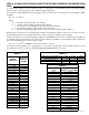
Table 1 can be used to select sizes of type M copper tubing as
well as PEX and PEX-AL-PEX tubing based on these limiting
velocities.
Example 2: Assume the target flow rate of 10 gpm from exam-
ple 1, and that copper tubing is used for the circuit.What is the
proper tube size based on keeping the flow velocity between
two and four feet per second?
Taco Radiant Made Easy Application Guide
Selecting Circulators
EFFECTIVE:August 15, 2005 SUPERSEDES: New
Technical Documents
TD10
Formula 1: f =
Q
500 x (∆T)
f = = = 10 gpm
Q
500 x (∆T)
100,000
500 x (20)
Supporting Technical Documents:
TD09 – Understanding Pump Curves
Taco Product Catalogs:
100-8.5 – “00” Series Cartridge Circulators
100-34 – 1400 Series High Capacity Circulators