
Manual


TD10 –4
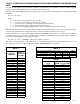
STEP 5: SELECT A SUITABLE TACO CIRCULATOR
Plot the target operating point just established on a graph
showing the pump curves of several “candidate” circulators
as shown in Figure 1.
Look for a circulator with a pump curve passing through, or
relatively close to, the target operating point. For our exam-
ple system, a Taco 0012 meets this criteria. So does a Taco
0010.
Because the curve for the 0012 is slightly above the target
operating point the flow rate in the system will be slightly
higher than the target value.This is not necessarily a prob-
lem. It means that a slight safety factor would be present to
cover for slightly greater installed piping lengths, or other
unforeseen conditions that might increase system head loss.
Think of it as analogous to selecting a boiler that has slightly
more heat output than the design heating load of the build-
ing in which it will be used.
The pump curve for the 0010 circulator passes just under
the target operating point. If this circulator were selected the
flow rate in the system would be slightly less than the target flow rate. If the drop in flow was limited to no more than
five percent the difference in the system’s thermal performance would be negligible, and thus the smaller circulator might
still be a suitable selection. However, it is generally considered poor practice to select a circulator that yields flow rates
less than the calculated target flow rate for the system.
Another option the designer could investigate before making the final circulator selection is using 1.25 copper tubing rather
than 1-inch tubing. Recall that the 1.25-inch tubing was a possibility based on flow velocities from Step 2. If 1.25-inch was
used, the revised head loss is found by returning to Step 4 and using the appropriate k-value for 1.25-inch tubing:
H
L
= k x c x L x (f
1.75
) = 0.000324 x 1.00 x 239 x 56.234 = 4.35 feet
Notice that head loss has decreased significantly based on the use of 1.25-inch rather than 1-inch tubing.The system’s target
operating point is now 10 gpm with an associated head loss of 4.35 feet.This is shown on the graph in Figure 2.
The new target operating point falls beneath the pump
curves for several more circulators including the Taco 005 or
Taco 007. These smaller circulators are less expensive and
use less electrical energy than the larger Taco 0012 and Taco
0010 models. It’s very likely that either of the smaller circu-
lators (005 or 007) used in combination with the 1.25-inch
tubing size would lower the overall life cycle cost of the pip-
ing system.
Hence, the designer has several possible circulator choices,
all of which could satisfy the target flow rate requirement of
10 gpm. The final decision often depends on weighing the
cost differences along with personal preferences. As is often
the case, no one circulator must be used to achieve accept-
able system performance. The situation is analogous to the
fact that an automobile can be equipped with several differ-
ent engine options and still yield acceptable performance.
12345678910
10
9
8
7
6
5
4
3
2
1
454035302520151050
0
5
10
15
20
25
30
35
003 006 008 005 007 0011 0010
0013
0012
0014
009
FLOW - M
3
H
FLOW - GPM
TOTAL HEAD - FEET
TOTAL HEAD - METERS
target operating point
Figure 1
12345678910
10
9
8
7
6
5
4
3
2
1
454035302520151050
0
5
10
15
20
25
30
35
003 006 008 005 007 0011 0010
0013
0012
0014
009
FLOW - M
3
H
FLOW - GPM
TOTAL HEAD - FEET
TOTAL HEAD - METERS
original target operating point
new target operating point
Figure 2