
Installation Manual

START UP:
Before operating the pump for the first time, check the following:
1. Is motor correctly wired for voltage in use? Warranty is void if motor is damaged due to improper electrical hook-up.
2. If a magnetic starter is used, see that the heater element is sized for the Service Factor load of the motor otherwise
nuisance tripouts may occur.
3. IMPORTANT: Couplers must be properly aligned and coupler inserts must be fully engaged in the hubs (no teeth show-
ing). Check alignment and spacing before and after initial start-up. Check the set screws on each coupler hub to ensure
that they are tightened securely.
4. Before starting motor, ascertain that pump is filled with water to lubricate the seal. Do not operate pump dry for motor
checkout.
LUBRICATION:
Pump is equipped with permanently lubricated ball bearings. Lubricate motor per instruction label attached to motor.
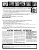
SEAL REPLACEMENT:
Seals used in these pumps are Type 21 design (see Photo A). Some models manufac-
tured between 2004 and 2008 used the Type 2100 design (photo B). These designs are
interchangeable.
To replace the water seal, the following steps must be observed:
1. Disconnect electrical connections. Relieve system pressure and drain water from body.
2. Remove motor assembly from bracket and bracket from pump body.
3. Place bracket in vertical position, impeller up and loosen screw at center of impeller
two turns (
7
⁄
16
Hex Head). This screw has a left-hand thread. Tap impeller at its out-
side diameter with handle of hammer to free tapered fit between shaft and impeller
and completely remove screw, washer and impeller (see Figure 2 on reverse side of
this Instruction Sheet).
4. Remove the complete rotating element, which includes the retainer, rubber bellows, carbon and spring (it may be nec-
essary to pry these components loose using a screwdriver). Remove the stationary seat from the recess in the end of
the bracket (again it may be necessary to pry it loose with a screwdriver, see Figure 3 on reverse side).
5. Thoroughly clean shaft sleeve and seat cavity.
Instruction Sheet
2
1
⁄
2
", 3" & 1600 Series Pumps
302-001
APPLICATION:
All pumps covered by this instruction sheet are designed for pumping water.
Working Pressure: 175 PSIG with cold water and
125 PSIG at rated temperature
Temperature: 250°F Standard
300°F with Hi-Temp Seal
INSTALLATION:
Install horizontally with the motor cradle under the motor as shown in the picture
to the right.
The casing can be rotated relative to the bracket for installation in vertical or horizontal pipe.
The pump must be installed far enough away from ceiling and walls to permit servicing of bracket and motor.
SUPERSEDES: July 1, 2009 EFFECTIVE: October 1, 2010
Plant ID# 001-972
CAUTION: UNDER NO CIRCUMSTANCES SHOULD ANY PART OF BRACKET OR MOTOR BE COVERED
WITH INSULATION. OBSERVE ALL APPLICABLE ELECTRICAL AND MECHANICAL CODES.
A
B
IMPORTANT NOTE: THE OLD SEAL SEAT MAY BE DIFFICULT TO SEE BUT NEEDS TO BE REMOVED BEFORE
INSTALLING NEW ONE (SEE CUT-AWAY VIEW IN FIGURE 3A).
CAUTION: DO NOT SUPPORT, SUSPEND OR BRACE MOTOR AND/OR BRACKET. SUPPORT
PROVIDED BY CASING IS SUFFICIENT FOR STRUCTURAL INTEGRITY OF THE PUMP.
121 through 138 & 1600 Series Pumps