
Install Instructions

Instruction Sheet
Boiler Feed Valves (Pressure Reducing Valves)
Models 329, 329-T and 335
Dual Controls
Models 334 and 334-T
1
02-006
SUPERSEDES: 102-006 dated January 1, 2003 EFFECTIVE: November 1, 2012
Plant I.D. 001-924
RATINGS:
Boiler Feed Valves (Reducing Valves):
Maximum Fluid Temperature 212°F (100°C)
Maximum Supply Side Pressure 100 psi (689 kpa)
Setting Range 10-25 psi (69-172 kpa)
Factory Setting of System Side 12 psi (83 kpa)
Dual Controls:
Maximum Fluid Temperature 212°F (100°C)
Maximum Supply Side Pressure 100 psi (689 kpa)
Relief Valve Set to Release at 30 psi (207 kpa)
DESCRIPTION:
The Boiler Feed Valves are adjustable pressure reducing
valves that automatically maintain system pressure. They
are equipped with a FAST FILL lever that can be used to
override automatic pressure regulation during purging.
329:
1
⁄
2
" union connection with a sweat tailpiece
at inlet end and a female NPT connection at
the outlet end.
329-T: same as 329 except the inlet union connec-
tion is threaded.
335:
3
⁄
4
" cast brass body with female NPT con-
nections at body ends.
The Dual Control consists of a 329 Boiler Feed Valve with
an in-line pressure relief valve connected at its outlet end.
334:
1
⁄
2
" union connection at inlet with a sweat
tailpiece and a female NPT connection at
the outlet end.
334-T: same as the 334 except the union end tail-
piece is threaded.
INSTALLATION:
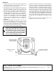
1. Install the Boiler Feed Valve or the Dual Control in a
horizontal position in the cold water supply pipe to the
boiler.
2. Install a shut-off valve on the upstream side of the
Boiler Feed Valve. This valve, provided for isolation pur-
poses during maintenance, must be open at all times
during operation so that the Boiler Feed Valve can
maintain pressure automatically.
3. Flush out the supply pipe to clear it of chips, scale, dirt,
etc. before connecting it to the inlet of the Boiler Feed
Valve.
4. Connect a pipe from the bottom “DRAIN” connection
of the Relief Valve in the Dual Control. Direct it to some
convenient open drain, such as a floor drain or set tubs.
Always obey local regulations. DO NOT install a valve
of any kind in the drain pipe. The pipe must always
pitch down from the valve, with no part of it above the
valve, and be no smaller in size than the valve drain
connection size.
SYSTEM
RETURN
HOT WATER
BOILER
TO
SYSTEM
TO
DRAIN
SHUT-OFF
VALVE
COLD WATER
SUPPLY
BOILER FEED
VALVE OR
DUAL CONTROL
Caution: Boiler Feed Valves and Dual Controls should only be installed by qualified heating professionals.
Consult local authorities for any code requirements in your area.