02-477 Installation & Operating Instructions FloodBreaker™ SUPERSEDES: November 26, 2013 Plant ID No.
Table of Contents Page 1. 2. 3. 4. 4.1 5. 5.1 5.2 5.3 5.4 5.5 5.6 5.7 5.8 6. 6.1 6.2 6.3 6.4 6.5 6.6 6.7 6.8 6.9 6.10 7. 7.1 7.2 7.3 8. 8.1 9. 10. 11. 12. 13. Safety information . . . . . . . . . . . . . . . . . . . . . . . . . . . . . . . . . . . . . . . . . . . . . . . . . . . . . . . . . . . . . . . . . . . . . 4 Application . . . . . . . . . . . . . . . . . . . . . . . . . . . . . . . . . . . . . . . . . . . . . . . . . . . . . . . . . . . . . . . . . . . . . . . . . . . 4 Factory Default Settings . .
Safety Requirements Consult local plumbing, building and electrical codes in your area before installing the FloodBreaker™. The FloodBreaker is for indoor use only and should only be installed by qualified professionals. These instructions are not intended to contradict any local building codes. These instructions should be considered in addition to local codes. Consult your local authority regarding any instructions contradictory to code requirements. Warning: The FloodBreaker must not be installed 1.
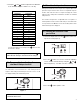
3. Inserting/Changing Batteries Insert the batteries prior to using the FloodBreaker. Open the battery door and remove the battery block. 4. General Operation The control consists of a two digit display and three push buttons (mode, up and a down button). Use the up or down button to adjust the values. to confirm and save the values or to scroll through Use the the menu items.
Once cycled through all three primary menus the keyboard returns to the locked position. If no button is pushed for 30 seconds the display goes blank and returns to the locked position. Note: If the FloodBreaker is attached to an external power source, the display always remains active. 5. User Menu 5.2 Setting the standard leak protection If you are not using an external power source, press any button to activate the display. LE appears in the display window.
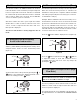
4. Using the and buttons adjust the FloodBreaker to the desired setting. See Table 1 for code key. 5.4 Vacation leak protection During periods when the house may be unoccupied a tighter leak protection may be desired.
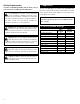
Table 2 (UL) Vacation Leak Settings Approximate Gallons –– Deactivated 1 3 2 5 3 8 4 11 5 13 6 16 7 18 8 21 9 24 10 26 5.8 Opening and closing the FloodBreaker button until reach1. Unlock the keyboard. Press the ing the manual menu identified as Ab (Figure 11). Figure 11 Note: When vacation leak protection mode is activated, it overrides any standard leak protection. 5.6 Deactivating vacation leak protection 2. Press the button again to view the current position. 3.
6.1 48 hour leak monitor The 48 hour monitor is an additional method to check for leaks. This function can be used when you may be away from home for longer than several hours and have not activated the vacation leak protection. When this monitor is activated and no water is drawn off for 48 hours, the FloodBreaker closes to isolate the system for 3 minutes. After three minutes the device opens again and verifies whether there is a flow of water.
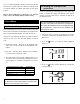
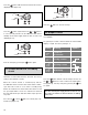
Press the button until the time-based flow rate menu is displayed as t2 (Figure 15). Figure 17 Press the button to save the change. Figure 15 Press the button again and use the or buttons to set how many minutes the FloodBreaker waits before shutting off the water supply when the flow exceeds 15.5 GPM (Figure 16). 6.6 Output contact This is a dry contact with a 24Volt/2amp maximum switching capability. The primary use for this contact would be an external alarm display or signal.
6.7 Internal alarm The FloodBreaker has an audible alarm that will sound when a leak is detected and the valve closes. Press the 6.8 In1 – Floor sensor Press the until 11 is shown (Figure 21). until bu is shown (Figure 19). Figure 21 Figure 19 Press the button again to make adjustments. Use the up or down button to activate (1) or deactivate (-) (Figure 22). Press the button again to make adjustments. Use the up or down button to activate (1) or deactivate (-) (Figure 20).
6.9 In2 – Input contact The In2 contact offers multiple input possibilities such as instant floor sensors, temperature probes, timers, radiocontrolled floor sensors, switch buttons, etc. None of these items are provided by Taco but are standalone contact devices. The contact is factory set to deactivate (--). Press the Settings 1-3 actuate the valve with an input signal as shown. A7 is displayed when activated. Reset the FloodBreaker by pressing the mode button.
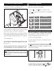
7.1 Software version Remove the two cover halves (Figure 27). Figure 25 Press the mode button to display the software version (Figure 25). 7.2 Battery power Figure 27 The key is located on the inner side of the left cover (Figure 28). Figure 26 Figure 28 Press the mode button to display the battery voltage remaining (Figure 26). Remove the locking clamp from the control head so that it can be lifted off. Lift off the control (Figure 29). 7.
Press the down button to change to “P1” and then press the mode button to save. Once the control unit has rotated to the open position and stopped it can be installed on the valve body. Align the valve stem and locating pin with the mating stem slot and locating notch on the control unit. Slide the control unit onto the valve stem. You may need to gently wiggle the control unit until it is fully seated. Place the locking clamp back into the clamp slots once the control unit is fully seated. 9.
11. Dimensions A G B DIMENSIONS (for reference only) F E Inches (mm) A 41⁄4 (108) B 15 16 C 41⁄8 (105) D 3 (76) ⁄ (24) E 123⁄32 (307) F 655⁄64 (174) G 447⁄64 (120) D C 12. Message Codes DISPLAY INDICATION POSSIBLE CAUSE POSSIBLE SOLUTIONS • Mechanism blocked • Remove blockage • Motor failed • Press the mode button to try again The turbine cannot rotate. • Turbine is blocked • Consult factory A3 A volume-base leak has been detected.
13. Installing the FloodBreaker For the most complete protection, the FloodBreaker should be installed on the home’s incoming water supply and as close to where the supply enters as possible. (Check with local authorities for any restrictions.) The FloodBreaker uses a universal body assembly and can be installed into either a vertical or horizontal pipe line as shown (Figure 32). The FloodBreaker universal body may now be attached to the tailpieces already installed in the piping as shown (Figure 32).