
Install Instructions


3
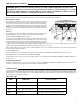
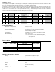
3-Way / 4-Way iSeries Mixing Valve Selection
Select the 3-way or 4-way iSeries Mixing Valve based on the Pressure Drop chart below.
Sequence of Operation
Power Up and Heat Request
Whenever the iSeries-S is powered up, the LED turns green and the control starts operation. The power to the iSeries-S may be
switched through an end switch (e.g. Taco ZVC/SR style zone control), a thermostat for intermittent operation, or the power source
may be connected directly to the iSeries-S for continuous operation.
Setpoint
The iSeries-S operates the valve to maintain a fixed setpoint. The setpoint temperature is set using the Setpoint
dial located on the top of the actuator. The setpoint range available is from 80ºF to 180ºF.
Boiler Protection
An optional boiler return sensor (Taco part #9300-2044RP) can be installed to provide boiler protection. When the boiler return tem-
perature is below 135ºF, the green LED flashes rapidly (reduced output) and the iSeries-S modulates towards the closed position in
order to allow the boiler temperature to recover.
Setback
The iSeries-S has a setback function used to lower the setpoint target. The setpoint target is lowered by 15ºF whenever there is a con-
tact closure across the SETBACK and SENSOR COMMON terminals.
80°F
90
100
150
110
120
130
140
160
170
180°F
SETPOINT
iSeries 3-way Valve Pressure Drop
Flow
GPM
1
⁄
2
" Sweat & Threaded
C
v
= 1.5
1
⁄
2
" Union
C
v
= 3.5
3
⁄
4
" Sweat & Threaded
C
v
= 3.5
3
⁄
4
" Union
C
v
= 4.5
1" Sweat & Threaded
C
v
= 4
1" Union
C
v
= 4.5
PSI Ft. Head PSI Ft. Head PSI Ft. Head PSI Ft. Head PSI Ft. Head PSI Ft. Head
1
⁄
2
0.11 0.26 0.02 0.05 0.02 0.05 0.01 0.03 0.02 0.04 0.01 0.03
1 0.44 1.03 0.08 0.19 0.08 0.19 0.05 0.11 0.06 0.14 0.05 0.11
2 1.78 4.10 0.33 0.75 0.33 0.75 0.20 0.46 0.25 0.58 0.20 0.46
4 — — 1.31 3.01 1.31 3.01 0.79 1.82 1.00 2.31 0.79 1.82
6 — — 2.94 6.78 2.94 6.78 1.78 4.10 2.25 5.19 1.78 4.10
8 — — 5.22 12.05 5.22 12.05 3.16 7.29 4.00 9.23 3.16 7.29
10 — — — — — — 4.94 11.39 6.25 14.42 4.94 11.39
12 — — — — — — 7.11 16.41 — — 7.11 16.41
iSeries 4-way Valve Pressure Drop
Flow
GPM
3
⁄
4
"
C
v
= 7.0
1"
C
v
= 9.3
1
1
⁄
4
"
C
v
= 17.5
PSI Ft. Head PSI Ft. Head PSI Ft. Head
1
⁄
2
0.01 0.01 0.00 0.01 0.00 0.00
1 0.02 0.05 0.01 0.03 0.00 0.01
2 0.08 0.19 0.05 0.11 0.01 0.03
4 0.33 0.75 0.18 0.43 0.05 0.12
6 0.73 1.69 0.42 0.96 0.12 0.27
8 1.31 3.01 0.74 1.71 0.21 0.48
10 2.04 4.71 1.16 2.67 0.33 0.75
12 2.94 6.79 1.66 3.84 0.47 1.08
14 4.00 9.24 2.28 5.27 0.64 1.48
16 — — 2.96 6.84 0.84 1.93
18 — — 3.76 8.70 1.06 2.44
20 — — — — 2.30 5.31