
Install Instructions

Listings/Approvals:
• UL Guide (NKPZ) for industrial control
equipment per UL Standard 508 Industrial
Control Equipment
• UL Guide (MFHX) for heating/cooling ap-
pliance switch per UL Standard 353 Limit
Controls
• CSA Class (321106) for industrial control
equipment per CSA Standard C22.2 No.
14-M Industrial Control Equipment
Maximum Service Pressure: 250 PSI
Enclosure:
NEMA Type 1 (For indoor use only)
Formed sheet metal with powdercoat finish.
Not for use in hazardous locations.
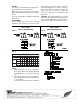
Contacts:
IFS01: One SPDT (Form C) switch
IFS02: Two sets of SPDT (Form C) switches
to provide versatility in wiring two separate
circuits.
15 Amps at 125/250VAC
.5 Amps at 125VDC
.25 Amps at 250VDC
Motor Ratings : 120VAC 240VAC
Horsepower : 1/8 1/4
AC F.L.A. : 3.8 2.9
AC L.R.A. : 22.8 17.4
Pilot Duty Rating : 125 VA 120/240 VAC
IFSH1/2 Contacts:
IFSH1: One SPDT (Form C) switch
IFSH2: Two sets of SPDT (Form C) switches
to provide versatility in wiring two separate
circuits.
22 Amps at 125/250VAC
Motor Ratings : 120VAC 240VAC
Horsepower : 1/2 1
AC F.L.A. : 9.8 8.0
AC L.R.A. : 58.8 48.0
Pilot Duty Rating : 125 VA 120/240 VAC
Ambient Temperature Range:
32°F/176°F (0°C/80°C)
Media Temperature Range:
32°F/250°F (0°C/121°C)
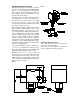
Pipe Connections:
1" NPT Brass on models IFSxxB
1" NPT 316 Stainless Steel on models
IFSxxS
Conduit Entrance: Two openings for 1/2" conduit
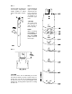
Usage: For pipe sizes 1" - 8"
Caution: This device is not intended for applica-
tions in explosive environments.
Note: IFSW Series available with NEMA 4 enclo-
sure for outdoor use. (See bulletins
#102-026 & #102-027 or Catalog 100-8.2).
GENERAL
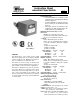
The Model IFS is a flow switch used in liquid
flow lines carrying water or any fluid not harmful
to brass, stainless steel, EPDM or fluorosilicone,
and not classified as a hazardous fluid.
This switch can serve as a way to start and stop
electrically operated equipment when a flow or no
flow condition occurs in a variety of applications.
This device is designed for use only as an operat-
ing control. Where an operating control failure
would result in personal injury and/or loss of prop-
erty, it is the responsibility of the installer to add
devices (safety, limit controls) that protect against,
or systems (alarm, supervisory systems) that warn
of control failure.
Instruction Sheet
Industrial Flow Switch
SUPERCEDES: 102-122 DATED January 1, 2002
# 5401110-REV E
EFFECTIVE: March 17, 2004
102-022
(IFS01 &
IFS02 ONLY)