
Install Instructions
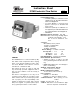

MOUNTING AND INSTALLATION
The IFSWS Series may be mounted in a hori-
zontal pipe line or a vertical pipe line with
upward liquid flow. It is not recommended for
installations where flow is downward. When
mounted in a horizontal pipe line the switch
should be mounted on the top side of the pipe
where it will be accessible. The switch will trip at
a lower flow rate than shown in Table 1.
Mount the device in a section of pipe where
there is a straight run of at least 5 pipe diameters
on each side of the flow switch. Do not locate
adjacent to valves, elbows or orifices. The switch
should be mounted so the terminals or wire leads
are easily accessible for wiring.
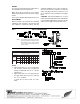
IFS models with flexible paddles are furnished
with 4 paddles. Rigid paddle models are fur-
nished with 2 paddles. For pipe sizes 1", 2", 3",
6" and 8", use the paddles provided. Intermedi-
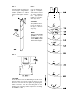
FIG. 2FIG. 1
Sensitivity Adjustment Note:
Turn sensitivity screw clockwise to increase the
flow rate required to activate the switch.
Turn sensitivity screw counter-clockwise to de-
crease the flow rate required to activate the
switch.
Turn radius = 1.88"
ate sizes may be trimmed from the appropriate
paddle using the paddle template in Fig. 5. The
paddle must not touch the inside of the pipe or
bind in any way. Paddles smaller than the ac-
tual pipe size should be used for added support
and higher sensitivity, see Fig. 3. The paddles
must be properly attached and the screw that
holds the paddle must be securely tightened.
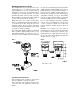
For a 1" pipe application mount in a standard
1"x1"x1" tee. Use a reducing tee for larger sizes
of pipe to keep flow switch close to pipe and
provide adequate paddle length in the flow
stream.
Example: Use a 2"x2"x1" tee for 2" pipe. A
weldolet may also be used. Screw the device into
the tee fitting as shown in Fig. 4. The flat of the
paddle must be at a right angle to the flow. The
arrow on the side of the bushing must point in the
direction of flow, see Fig. 1.