
Install Instructions

WIRING
Use properly rated temperature supply wire for
the anticipated service temperature.
Make all electrical connections in accordance
with the National Electrical Code and local regu-
lations.
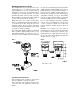
See Fig. 6 for diagram illustrating switch action.
ADJUSTMENT
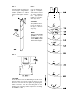
Remove switch cover and turn the sensitivity
adjusting screw clockwise to increase the flow
rate required to actuate the switch. Turn the
sensitivity adjusting screw counter-clockwise to
decrease the flow rate required to actuate the
switch. (See Fig. 6.) Be sure to replace the cover
upon completion of the installation and adjust-
ment.
CAUTION: Check the installation for "no-flow"
switch operation. Make appropriate adjustments
to the sensitivity adjustment screw to be sure the
switch restores fully at the desired flow rate.
FIG. 6 SWITCH INFORMATION
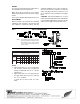
TABLE 1
NOTES:
1. Typical flow rates for 1" to 1 1/2" pipe sizes
are averages which may vary approxi-
mately ±1 GPM with the use of a bronze
reducing tee.
2. Typical flow rates for 2" to 8" pipe sizes are
averages which may vary ±10% with the
use of a 1" weldolet.
(*) Flow rates for these sizes are calcu-
lated.
SNOITACIFICEPS
hctiwSetautcAotderiuqeRMPG-setaRwolFlacipyT
)snoitallatsniepiplacitrevroF(
)sehcni(eziSepiP14/112/1122/12345*68*
muminiM
tnemtsujdA
wolF
esaercnI
5.45.40.65.75.3181530507012
wolF
esaerceD
5.35.30.55.55.931520406091
mumixaM
tnemtsujdA
wolF
esaercnI
5.90.015.310.020.920507021081014
wolF
esaerceD
0.75.85.015.810.625456501061083
NOTE: Turn sensitivity screw clockwise to increase
the flow rate required to activate the switch.
Turn sensitivity screw counter-clockwise
to decrease the flow rate required to acti-
vate the switch.