
Install Instructions


Application
The Taco LeakBreaker™ is a leak detection and water shutoff
device. It is designed to detect a water leak and shutoff the incom-
ing water supply to a water heater. It is suitable for use with many
o
ther water appliances that have a 3/4" (or smaller) connection
requiring leak protection.
Ease of Installation / Operation
The valve can be installed in either vertical or horizontal piping and
in any direction or orientation. LeakBreaker
T
M
consists of a control
panel, full port electrically actuated ball valve, floor sensor and is
powered by batteries, AC adaptor or both. The components are
connected with easy to use plug in quick connects. A multi- func-
tion LED on the control module identifies the current state of the
LeakBreaker and aides with troubleshooting.
Valve Installation
1. Shut off the main water supply.
2. Open a fixture nearest the water heater to relieve water pressure.
3. Install the LeakBreaker valve into the cold water supply to the
water heater.
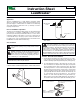
Actuator Removal and Installation
1. Actuator Removal: Remove the valve actuator prior to solder-
ing by pushing in and holding the release clip at the front of the
actuator and lifting upward approximately 3⁄4" (see Figure D).
To re-assemble the actuator to the valve body: Position actu-
ator such that the “D” shaped valve stem aligns properly with
the “D” shaped actuator drive cavity. (Note: The “D” shaped
stem design allows for correct insertion every time.) Next, slide
the valve stem into the actuator cavity, push in and hold the
release clip until the actuator slips over the valve locking posts
(see Figure D). Once the actuator is flush to the valve body, let
go of the release clip. Using very little force, try to take the
actuator off of the valve body without using the release clip.
Both locking posts should be firmly attached to the actuator. If
the actuator slides up the stem, repeat the assembly process.
Instruction Sheet
LeakBreaker
™
102-506
SUPERSEDES: NEW EFFECTIVE: August 1, 2016
Plant ID No. 001-4237
Warning: Never place any body parts or objects
into the valve opening, doing so may result in severe
injury!
Wall mounted
control
Floor sensor
2.
Step 2:
Move actuator upward approxi-
mately 3/4”
Step 1:
Push in and hold release clip
at the front of the actuator
Locking Post
Figure D:
Actuator Removal
Note: Depending on your piping system, additional fittings not
supplied with this product may be required.
CAUTION: If using a threaded to sweat adaptor on
the valve installation, the actuator must be removed
from the valve body before soldering (see instructions
for removing actuator). The ball valve must be in the full open
position before soldering.The valve is shipped in the closed
position. Use of a solder with a melting point below 600°F is
recommended. Do not overheat! Make sure the ball valve is in
the FULL OPEN position during soldering. Direct flame tip away
from the center of the valve. Cool valve quickly with a wet cloth.
Caution: Installation should only be performed by qual-
ified persons familiar with normal plumbing practices.
These instructions should be considered in addition to
local codes. Consult your local authority regarding any instruc-
tions contradictory to code requirements.
A
Taco Family Company